Guard for connection point of adjoined wire connectors

a technology of connecting point and adjoining wire, which is applied in the direction of coupling device connection, coupling/disconnecting parts, electrical apparatus, etc. it can solve the problems of inability to generate enough power economically, damage to the system, and inability to prevent inadvertent disengagement, so as to prevent accidental disengagement, prevent accidental disengagement of connectors, and convenient use

Active Publication Date: 2013-04-02
SHOALS TECH GROUP
View PDF11 Cites 32 Cited by
  • Summary
  • Abstract
  • Description
  • Claims
  • Application Information

AI Technical Summary

Benefits of technology

[0010]The present invention is directed to a guard that quickly fits around the junction of joined connectors. The guard is essentially two cylinders which are joined in an end-to-end orientation with a tabbed gap there between, to form one discontinuous cylinder. The resulting longitudinally split, discontinuous cylinder has a hinge joining two halves of the cylinder longitudinally, and spaced irreversibly locking mechanisms joining the other halves of the cylinder when the cylinder is in the closed position. The tabs connecting the two cylinders can be intentionally broken, but are strong enough to prevent accidental exposure of the surrounded junction.
[0011]Accordingly, one aspect of the present inventions is to provide a connector guard that is easy to use and prevents accidental disengagement of connectors. It is also an aspect of the present inventions to provide a device that can be quickly and easily removed when desired, by using common electrical tools. Another aspect is to be able to expose the underlying connector without actually removing the invention, by twisting the device. Another aspect is providing frictional grips within the device to prevent the connection from slipping around.

Problems solved by technology

It is considered desirable from an environmental and political standpoint, but perhaps not economically feasible for generating enough power to make a meaningful contribution to the grid.
However, this unfortunately also creates the possibility of inadvertent disengagement, especially when wiring architecture is above ground, as it commonly is, where people can trip on the wires.
Such a disconnection may simply temporarily cut off one solar panel in an array, or may be catastrophic with respect to widespread damage to the system, or even risk of electrocution.
Preferably this device locks into place and is difficult to accidentally remove.

Method used


Image

  • Guard for connection point of adjoined wire connectors
  • Guard for connection point of adjoined wire connectors
  • Guard for connection point of adjoined wire connectors

Examples


Embodiment Construction

[0023]In the following description, like reference characters designate like or corresponding parts throughout the several views. It should be understood that the illustrations are for the purpose of describing a preferred embodiment of the inventions and are not intended to limit the inventions thereto.

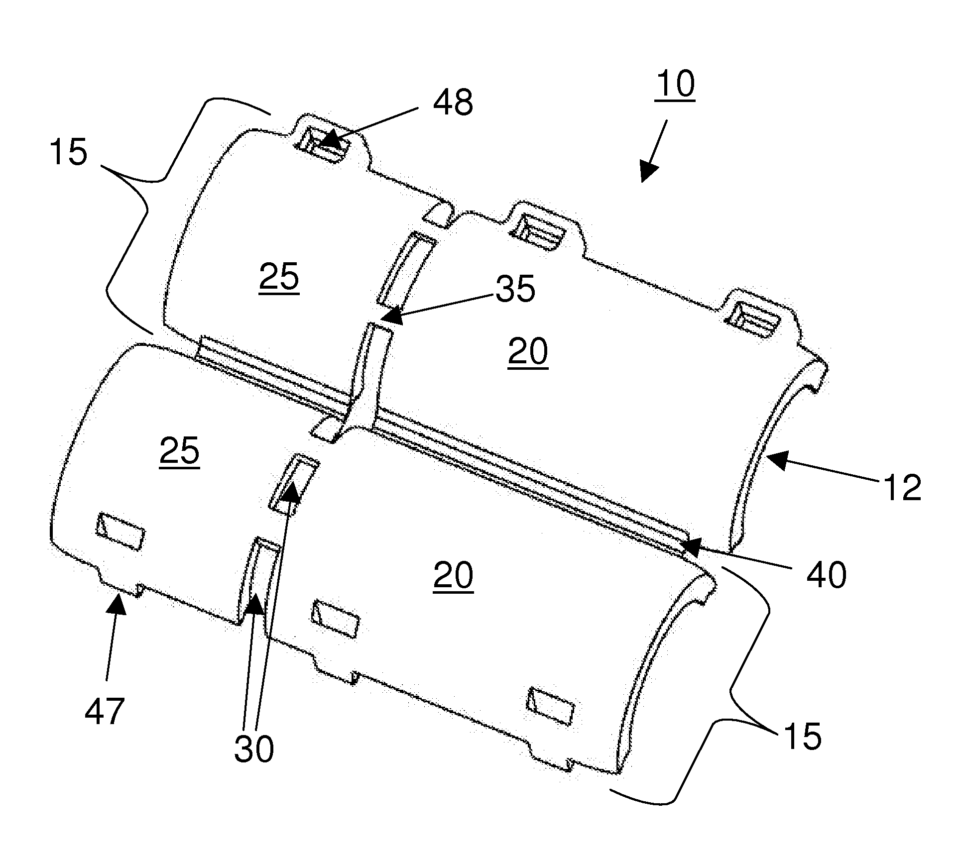
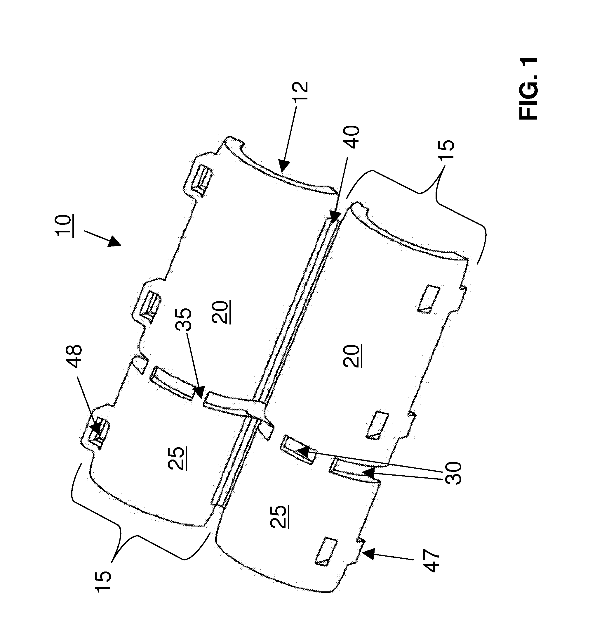
[0024]As best seen in FIG. 1, guard 10 generally includes two semi-cylindrical sections 15, 15, that are joined together at hinge 40. As used herein “semi-cylindrical” conceptually refers to approximately half, or approximately 180°, of a generally cylindrical or tubular structure that has been longitudinally divided. It should be understood that “semi-cylindrical” does not preclude breaks in symmetry such as planar sections or the addition of structures such as locking mechanisms, tabs and the like. Semi-cylindrical sections 15, 15 each include large section 20 and small section 25, which are connected to each other by at least one tab 35. Two tabs per section 15, for a total of fou...


PUM


Abstract

A cylindrical guard is used for protecting the electrical junction between connectors. The guard is essentially two split cylindrical sections oriented end-to-end with breakaway tabs therebetween. The split cylindrical pieces are hinged, and substantially irreversibly lock together in a “clamshell” like fashion. The resulting guarded junction is less likely to be accidentally disengaged, thereby protecting both property and life. The guard can be removed by cutting, or broken and moved to expose the underlying junction by severing the breakaway tabs.

Description

BACKGROUND[0001](1) Field[0002]The present invention relates generally to devices that protect wiring assemblies and, more particularly, to a hinged, split, tubular structure that irreversibly snaps onto the connection point of two adjoined wire connectors.[0003](2) Related Art[0004]The invention discussed herein can be used with connectors disclosed in U.S. patent application Ser. No. 12 / 502,395, pertaining to “Low Leakage Electrical Joints and Wire Harnesses, and Method of Making the Same”, filed on Jul. 14, 2009, which is hereby incorporated by reference.[0005]Solar power has long been considered a niche utility. It is considered desirable from an environmental and political standpoint, but perhaps not economically feasible for generating enough power to make a meaningful contribution to the grid. However, as the problems associated with our dependence on fossil fuels have become better understood, more attention has been paid to so-called alternative energy such as solar power. ...

Claims


Application Information

Patent Timeline
Patent Type & Authority Patents(United States)
IPC IPC(8): H01R13/639
CPCH01R13/639
Inventor SOLON, DEAN
Owner SHOALS TECH GROUP
Why Eureka
Try Eureka