Electric brake

a technology of electric brakes and brake cylinders, which is applied in the direction of brake cylinders, anti-theft devices, instruments, etc., can solve the problems of increased pad gap, increased braking time, and variable degree of deceleration of vehicles, so as to secure sufficient braking force and responsiveness, and good accuracy

Active Publication Date: 2013-04-30
HITACHI LTD
View PDF20 Cites 12 Cited by
  • Summary
  • Abstract
  • Description
  • Claims
  • Application Information

AI Technical Summary

Benefits of technology

[0008]Therefore, the present invention has been made in view of the above problem, and its object is to provide an electric brake apparatus which can estimate the temperature of the brake pad with good accuracy without using a temperature sensor and can secure sufficient braking force and responsiveness even in a situation where the temperature of the brake pad varies.
[0014]In addition, it is preferable that the drive controller changes the position of the piston at the time of starting a holding operation of the parking brake mechanism based on the maximum braking start position. In this way, it is possible to provide the electric brake apparatus which can secure necessary and sufficient braking force of the parking brake even in a situation where the temperature or the amount of wear of the brake pad varies after the parking brake is set.

Problems solved by technology

If the braking is released, the pad gap is increased due to thermal contraction of the brake pad in connection with cooling thereof, and wasteful time until starting the braking will be increased.
Further, if the temperature of the brake pad changes, the coefficient of friction between the brake pad and the disc rotor changes, and therefore the degree of deceleration of the vehicle may vary even when the brake pad is pressed with the same thrust.
Furthermore, if the temperature of the brake pad is lowered during parking braking and the thermal contraction is caused thereby, the thrust decreases, and therefore, the parking brake needs to be set with great braking force in advance in order to compensate the decrease of the thrust, which promotes increase of the electric power consumption and wear of mechanical components.
However, the temperature detection by a temperature sensor in the above conventional art leads to complication of the structure and increase in size of the actuator.
Further, if a temperature sensor is assembled in the disc rotor and the brake pad which are expendable parts, there is the problem that not only manufacturing cost, but also maintenance cost increase.
On the other hand, in the case of a temperature estimation method utilizing heat energy balance as in the above conventional art, it is difficult to estimate the pad temperature accurately since the heat energy balance is affected not only by outside air temperature and vehicle wind, but also by natural wind, road surface temperature and the like.
Particularly when the electric brake apparatus is left for a long time after its power source is turned off, the estimation error increases, which makes it more difficult to grasp the heat energy balance accurately.
Accordingly, it is difficult to estimate the pad temperature with good accuracy under all circumstances by the temperature estimation method based on the heat energy balance.

Method used


Image

  • Electric brake
  • Electric brake
  • Electric brake

Examples


Embodiment Construction

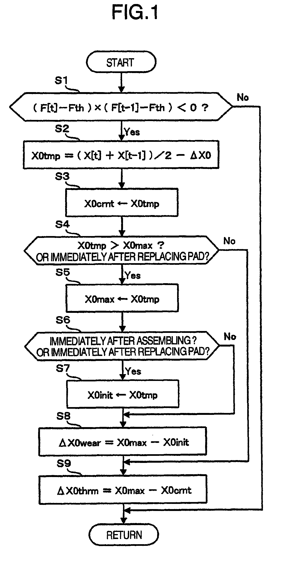
[0022]FIG. 1 shows an embodiment of a brake apparatus of the present invention.

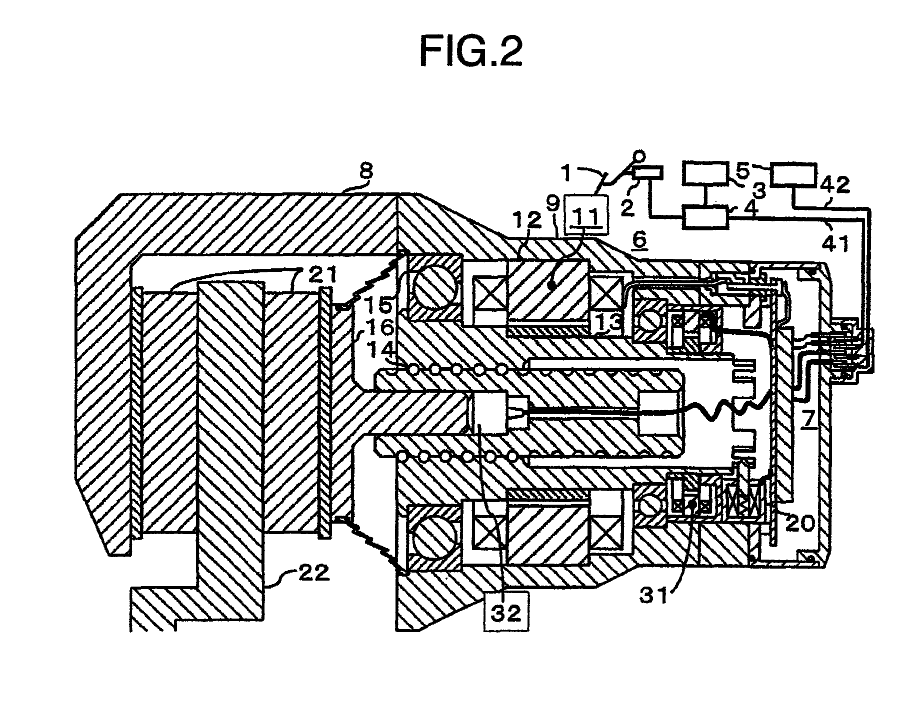
[0023]The brake apparatus comprises a brake pedal 1, a pedal sensor 2 for detecting the stepping amount of the brake pedal, an operating state detection unit 3, a vehicle motion controller 4 for calculating braking force, an electric power supply 5, an actuator 6 which is an electric braking force generating mechanism, a drive controller 7 for driving the actuator 6 and for transmitting and receiving a signal, and a caliper 8.

[0024]The actuator 6 comprises a housing 9, a motor 11, a stator 12 which is a fixing part of the motor 11 to the housing 9, a motor rotor 13 which is a rotating part of the motor 11, a screw portion 14 for converting rotation of the motor rotor 13 to linear motion, a bearing 15 supporting the motor rotor 13, a piston 16 generating thrust from the rotational power of the motor rotor 13, a parking brake mechanism 20 for mechanically fixing the position of the motor rotor 13 and the pi...


PUM


Abstract

Provided is an electric brake capable of accurately estimating the brake pad temperature and securing a sufficient braking force and response. An electric brake has a disc rotor rotating with a wheel, an actuator for rectilinearly actuating a piston in the axial direction of the disc rotor by using an electric motor, a drive controller for controlling the drive of the actuator, a brake pad pressed by the piston to give a frictional resistance to the disc rotor in the direction of rotation, and a braking start position detector for detecting a braking start position of the piston where the disc rotor is brought into contact with the brake pad. The drive controller stores the braking start position detected by the braking start position detector as the maximum braking start position. When the braking start position shifts in the pressing force-increasing direction, the drive controller updates the value stored as the maximum braking-start position.

Description

TECHNICAL FIELD[0001]The present invention relates to a brake apparatus for an automobile, and particularly to an electric brake apparatus which generates braking force using an electric motor.BACKGROUND ART[0002]Conventionally, there is known development of an electric brake apparatus in which an electric motor is rotationally driven depending on the amount of stepping of a brake pedal to generate braking force using the rotational torque of the electric motor. For example, the electric brake apparatus proposed in JP-A-2001-32868 comprises an actuator having an electric motor, and is adapted to apply braking force to a wheel by pressing a brake pad against a disc rotor depending on the amount of stepping of a brake pedal.[0003]The electric brake apparatus in the above conventional example uses the position of the brake pad at the time of releasing thrust detected by a thrust sensor when braking is finished as a braking start position; controls a gap between the brake rotor and the ...

Claims


Application Information

Patent Timeline
Patent Type & Authority Patents(United States)
IPC IPC(8): F16D66/02
CPCB60T13/741F16D65/18F16D2066/003F16D2066/005F16D2121/24F16D2125/40
Inventor YOKOYAMA, ATSUSHIKAWAHARA, YOSHINARIKURAGAKI, SATORU
Owner HITACHI LTD
Why Eureka
Try Eureka