Zoom lens barrel

a zoom lens and barrel technology, applied in the field of zoom lens barrels, can solve the problems of easy generation of backlash between linear cylinder and cam cylinder in a radial direction, heavy lens barrels, and deterioration of optical performance, so as to suppress backlash, improve linear cylinder fitting accuracy, and suppress lens unit tilt

Inactive Publication Date: 2013-06-04
CANON KK
View PDF5 Cites 3 Cited by
  • Summary
  • Abstract
  • Description
  • Claims
  • Application Information

AI Technical Summary

Benefits of technology

[0009]The present invention provides a zoom lens barrel that suppresses a backlash in a radial direction of a linear cylinder and a cam cylinder and improves a fitting accuracy of the linear cylinder and the cam cylinder to suppress the tilt of a lens unit to improve an optical performance, and that achieves a smooth zoom operation even when a lens holding frame has an impact.

Problems solved by technology

However, in the lens barrel disclosed in Japanese Patent Laid-Open No. 2005-017980, a backlash between the linear cylinder and the cam cylinder in a radial direction is easily generated at an end of a side where the whole unit cam groove is provided and an end of the opposite side in the optical axis direction.
As a result, the lens unit is also tilted since the cam cylinder is tilted, and therefore an optical performance may be deteriorated.
However, a lens barrel gets heavy when the magnification is higher, and the impact which is given by the drop is large.
However, in the lens barrel disclosed in Japanese Patent Laid-Open No. 2010-8802, although it is strong for the drop from the cam groove of a cam follower pin, a dent is formed on the cam groove when the impact is given.
Therefore, when the cam follower pin passes the cam groove having the dent after the impact is given, the image shake is generated and it is difficult to perform a smooth zoom operation.

Method used


Image

  • Zoom lens barrel
  • Zoom lens barrel
  • Zoom lens barrel

Examples


Embodiment Construction

[0036]Exemplary embodiments of the present invention will be described below with reference to the accompanied drawings. In each of the drawings, the same elements will be denoted by the same reference numerals and the duplicate descriptions thereof will be omitted.

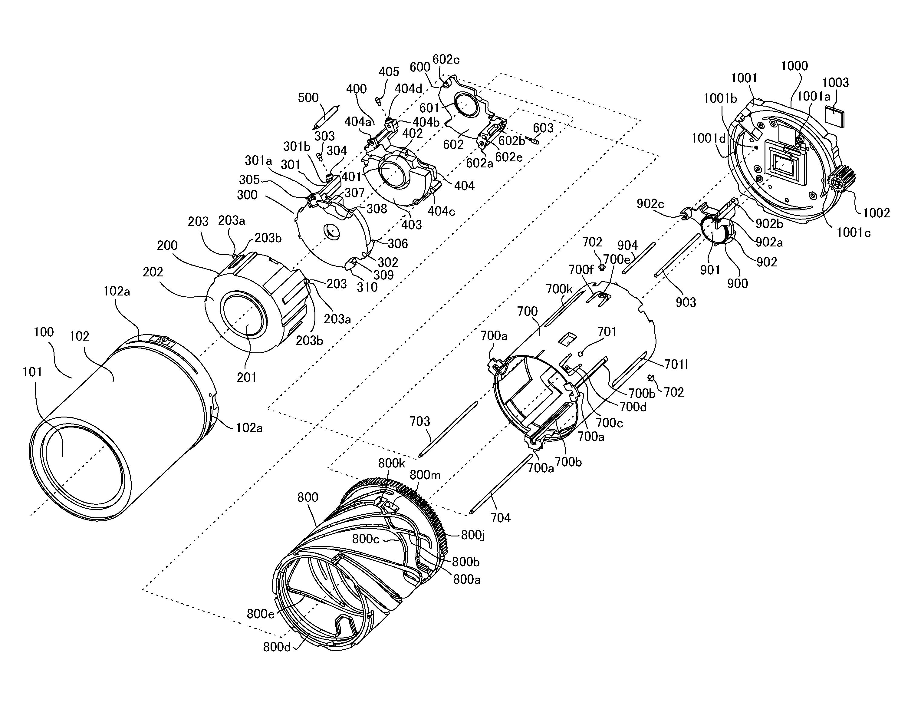
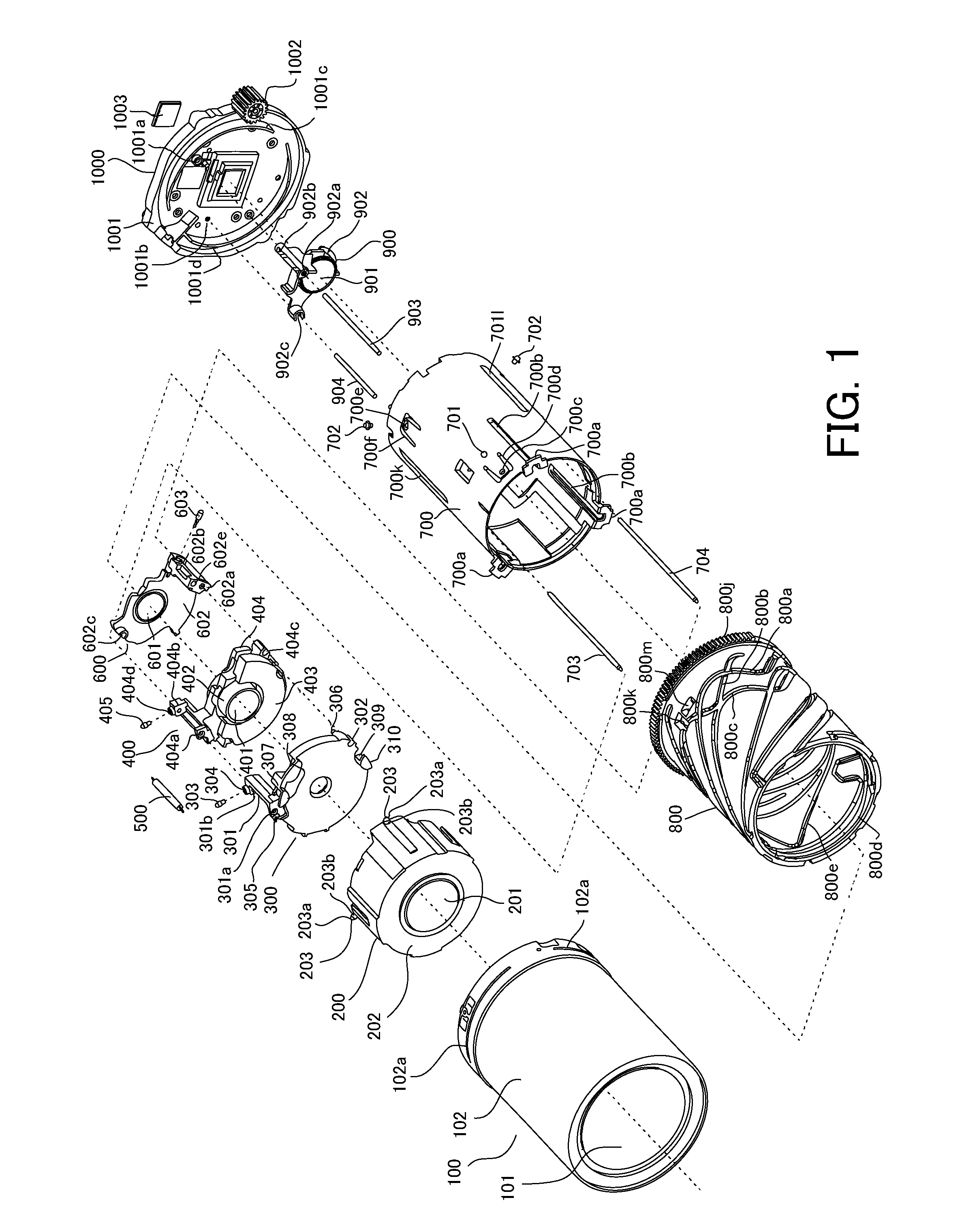
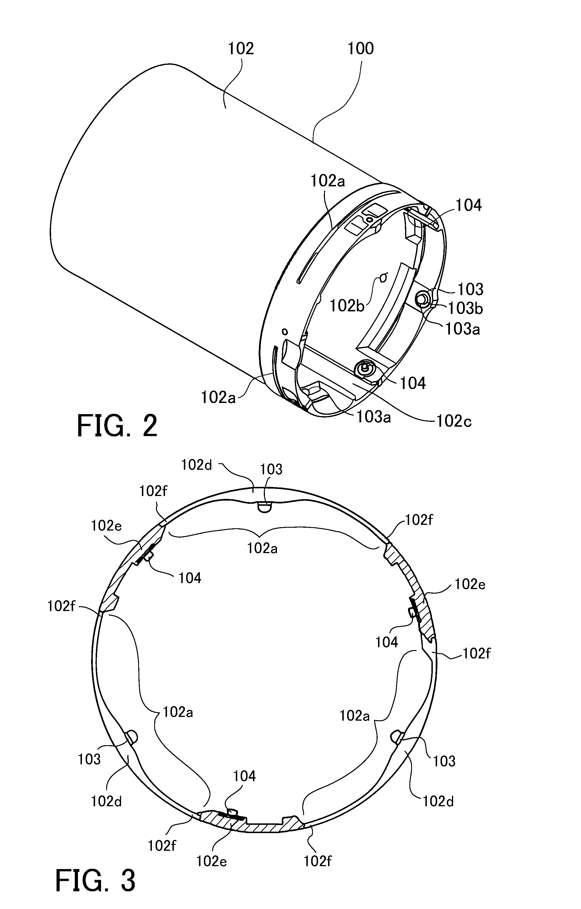
[0037]First of all, a configuration of a zoom lens barrel in the present embodiment will be described. FIG. 1 is an exploded perspective view illustrating a whole of the zoom lens barrel. FIG. 2 is a perspective view illustrating a first unit. FIG. 3 is a cross-sectional view of a first unit cylinder. FIGS. 4A and 4B are perspective views illustrating an integration unit that is configured by stacking a stop and shutter unit, a third unit, and a fourth unit. FIG. 5 is a perspective view illustrating a linear cylinder. FIGS. 6A and 6B are development views of an outer surface of a cam cylinder (FIG. 6A) and an inner surface of the cam cylinder (FIG. 6B). FIG. 7 is a perspective view illustrating the cam cylinder.

[0038]In F...


PUM


Abstract

A zoom lens barrel includes a base member 1001, a linear cylinder 700 fixed on the base member 1001, a cam cylinder 800 configured to be rotatable with respect to the linear cylinder 700, a ball member 701 and a pin member 702 provided on the linear cylinder 700, and a plurality of optical component units. The cam cylinder 800 includes a cam groove 800d that the ball member 701 contacts and that determines a position in an optical axis direction of the cam cylinder 800 with respect to the linear cylinder 700, and a cam groove 800i that the pin member 702 engages with in a radial direction of the cam cylinder 800 and that the pin member 702 contacts in two directions different from each other that are the optical axis direction.

Description

BACKGROUND OF THE INVENTION[0001]1. Field of the Invention[0002]The present invention relates to a zoom lens barrel that extends in an optical axis direction to be able to perform a zoom operation and to be retracted in a lens barrel body.[0003]2. Description of the Related Art[0004]Previously, in order to significantly move a lens unit in an optical axis direction to change a focal length, a zoom lens barrel has included a linear cylinder and a cam cylinder that is fitted on an outside diameter or an internal diameter of the linear cylinder to be supported so as to be rotatable around an optical axis and movable in the optical axis direction.[0005]Japanese Patent Laid-Open No. 2005-017980 discloses a lens barrel that includes a whole unit cam groove and a whole unit pin in order to move a cam cylinder with respect to a linear cylinder. It also discloses a configuration in which a whole unit auxiliary pin cam groove and a whole unit impact cam groove are provided adjacent to the who...

Claims


Application Information

Patent Timeline
Patent Type & Authority Patents(United States)
IPC IPC(8): G02B15/14G02B7/02
CPCG02B7/102G03B17/14G03B17/02
Inventor TSUJI, KANJIUEMURA, KOHEI
Owner CANON KK
Why Eureka
Try Eureka