
Quenching and tempering heat treatment device

A heat treatment device, quenching and tempering technology, applied in the direction of quenching device, heat treatment furnace, heat treatment equipment, etc., can solve the problems of long time, unstable product hardness, wide control range, etc., achieve enhanced hardness stability and improve energy utilization The effect of increasing the rate and improving the accuracy of the straight line

Active Publication Date: 2017-11-21
DALIAN DONGFEI SPECIAL STEEL PRODS
View PDF5 Cites 2 Cited by
  • Summary
  • Abstract
  • Description
  • Claims
  • Application Information

AI Technical Summary

Problems solved by technology

[0002] In heat treatment of high alloy steel, how to ensure the high linear precision and hardness stability of the steel is the main problem. Although there are ready-made heat treatment equipment for high alloy steel, the existing equipment is relatively complicated and huge. Once the equipment Fault maintenance is complicated and takes a long time, and the whole heat treatment process is cumbersome, the scope of control is too wide, there are many uncertain factors in the whole process, it is not easy to control, and it is easy to produce defective products due to equipment failure and process parameter changes; also due to the equipment itself The limitation of the product is that the product is bent and the hardness of the product is unstable; moreover, the energy consumption in the production process of the equipment is huge

Method used


Image

  • Quenching and tempering heat treatment device
  • Quenching and tempering heat treatment device
  • Quenching and tempering heat treatment device

Examples


Embodiment

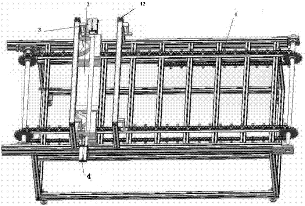
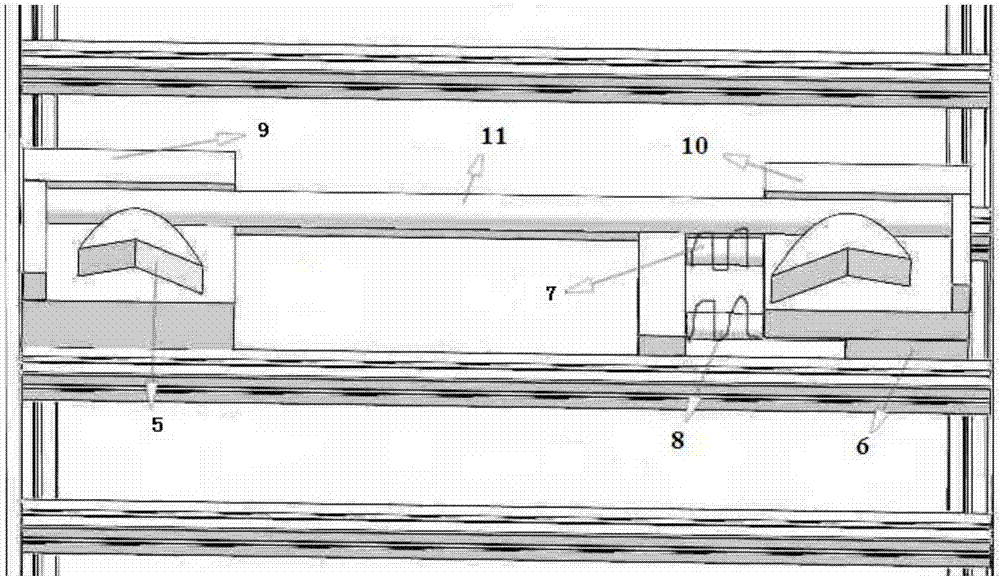
[0022] A quenching and tempering heat treatment device, including an integral transmission mechanism, a clamping and straightening mechanism, an electrode automatic connection mechanism, a heating mechanism, a cylinder pressing mechanism and a sensor, the clamping and straightening mechanism includes a pressing cam, a fixed end, a movable end, Springs, guide columns and sliders, and pressing cams are set on the support table at both ends of the clamping and straightening mechanism to clamp steel materials. One end of the clamping and straightening mechanism is the fixed end, and the other end is the movable end. The support at the movable end Two sliders are installed below the table, and the movable end moves back and forth on the guide post through the sliders to make the spring compressed and stretched. The electrode automatic connection mechanism is a telescopic connecting rod, and an electrode head is arranged under the telescopic connecting rod, and the electrode head is ...


PUM


Abstract

The invention relates to heat treatment processing equipment, and in particular to a quenching and tempering heat treatment device. The quenching and tempering heat treatment device comprises an integral transmission mechanism, a clamping and straightening mechanism, an electrode automatic connecting mechanism, an air cylinder clamping mechanism, a heating mechanism and a sensor, wherein the clamping and straightening mechanism comprises clamping cams, a fixed end, a movable end, springs, guiding posts and a sliding block; the clamping cams are arranged on supporting table surfaces of two ends of the clamping and straightening mechanism; one end of the clamping and straightening mechanism is the fixed end, and the other end is the movable end; the sliding block is arranged under the supporting table surface of the movable end. According to the quenching and tempering heat treatment device disclosed by the invention, the clamping and straightening mechanism is used for stretching and straightening a steel material by virtue of a spring force while quenching processing is carried out on the steel material, so that collapse and bending are prevented from being formed during a heating process of the steel material; the bending defect of the steel material after the processing of other heat treatment equipment is solved, and the linear accuracy of the steel material is increased; the quenching and tempering heat treatment device enables a whole produciton process to be free of production assistance items, so that the enery utilization rate is greatly increased, energy is saved, and the environment is protected.

Description

technical field [0001] The invention relates to heat treatment processing equipment, in particular to a simple device for high alloy steel pipeline quenching and tempering heat treatment processing. Background technique [0002] In heat treatment of high alloy steel, how to ensure the high linear precision and hardness stability of the steel is the main problem. Although there are ready-made heat treatment equipment for high alloy steel, the existing equipment is relatively complicated and huge. Once the equipment Fault maintenance is complicated and takes a long time, and the whole heat treatment process is cumbersome, the scope of control is too wide, there are many uncertain factors in the whole process, it is not easy to control, and it is easy to produce defective products due to equipment failure and process parameter changes; also due to the equipment itself The limitation of the product is that the product is bent and the hardness of the product is unstable; moreover...

Claims


Application Information

Patent Timeline
Patent Type & Authority Applications(China)
IPC IPC(8): C21D1/62C21D9/00
CPCC21D1/62C21D9/0018C21D9/0062
Inventor 贾东霞宁甲明金波王克孙汉新任洪亮
Owner DALIAN DONGFEI SPECIAL STEEL PRODS
Learn More