Camera and display control method of the same

a technology of display control and camera, applied in the direction of color television details, television system details, television systems, etc., can solve the problems of difficult to make an image worth viewing, difficult to fix start timing and end timing, and difficult to endure monotonous images

Active Publication Date: 2013-06-25
OM DIGITAL SOLUTIONS CORP
View PDF17 Cites 11 Cited by
  • Summary
  • Abstract
  • Description
  • Claims
  • Application Information

AI Technical Summary

Benefits of technology

[0008]The present invention aims for providing a camera which is suitable for a photographer to enjoy a moving image together when viewing an image such as an intentionally photographed still image, and for providing a display control method of the camera.

Problems solved by technology

On the other hand, in moving image photographing, it is difficult how to fix start timing and end timing and a movie camera is used frequently in a formalized case such as an athletic festival and a wedding ceremony.
Further, except when detailed rendering is preliminarily determined, a photographed moving image has little variety and it is very difficult to make it an image worth viewing.
This is because it is difficult to endure the monotonous image for a user accustomed to viewing a moving image in which composition changes frequently as in a TV program.
Moreover, although a colorful expression can be obtained by the change of photographing parameters, it is difficult for an amateur user to do it.
In this manner, although the moving image photographing is difficult for the typical user, the still image has a limitation for obtaining the colorful expression on the other hand.

Method used


Image

  • Camera and display control method of the same
  • Camera and display control method of the same
  • Camera and display control method of the same

Examples


Embodiment Construction

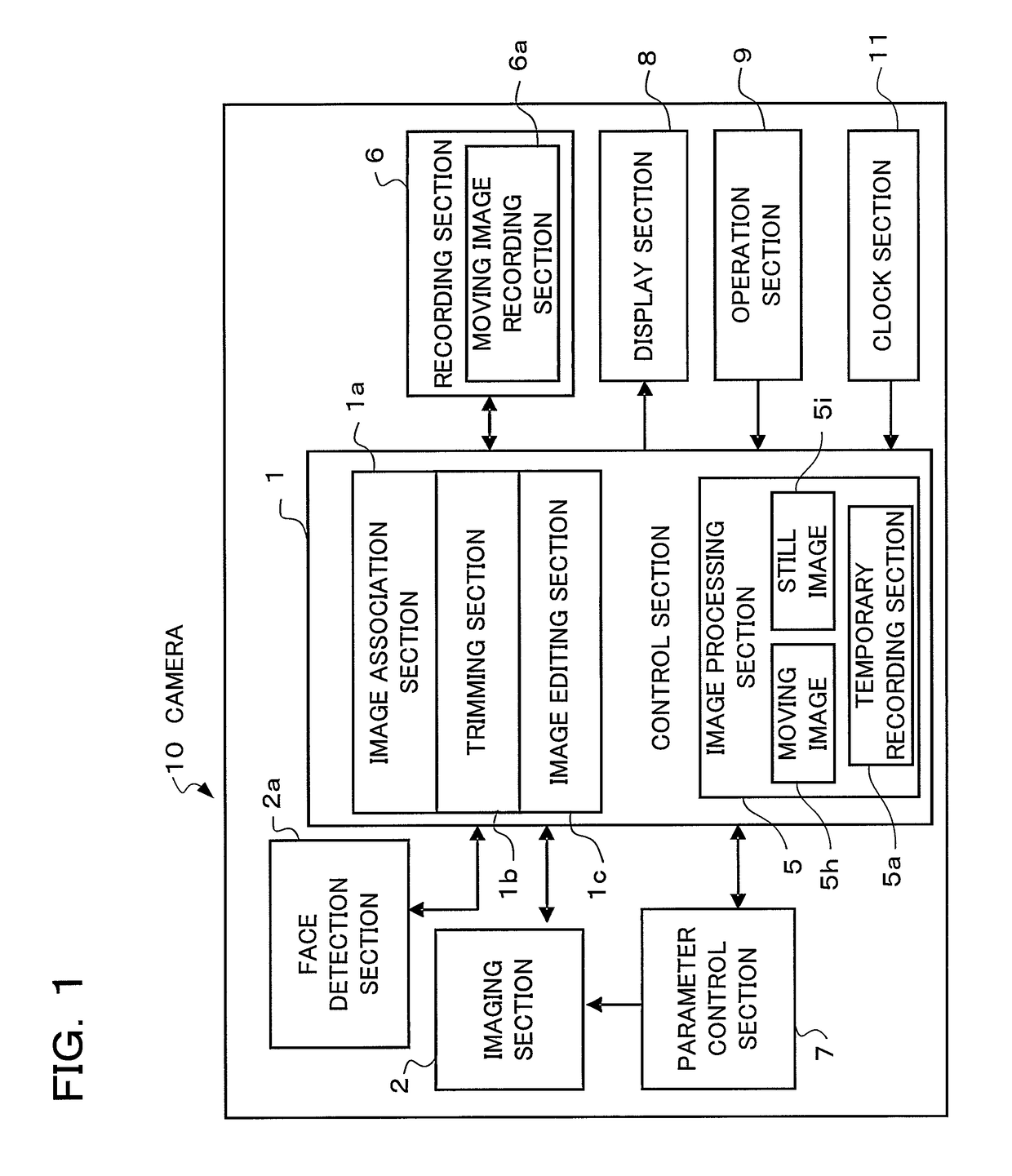
[0023]Hereinafter, preferred embodiments will be explained using a camera to which the present invention is applied, according to the drawings. FIG. 1 is a block diagram showing an electrical circuit of a camera 10 according to an embodiment of the present invention. The camera 10 is a digital camera and configured with a control section 1, an imaging section 2, a face detection section 2a, a recording section 6, a parameter control section 7, a display section 8, an operation section 9, a clock section 11, and the like.

[0024]The imaging section 2 includes a photographing lens (zoom lens) having a zoom function, an exposure control section such as a shutter and an aperture, an imaging element, a driving and reading-out circuit of the imaging element, and the like, and converts an object image formed by the photographing lens into image data with the imaging element and outputs this image data. Further, the photographing lens of the imaging section 2 includes a focusing lens and a me...


PUM


Abstract

A camera according to the present invention comprises: an imaging section converting an object image into image data; a storage section storing still image data of a still image obtained by the imaging section, thumbnail image data of the still image, and moving image data of a moving image which has been photographed at timing at least either before or after photographing of the still image; a display section performing display of one or more thumbnail views according to the thumbnail image data; and a display control section, when one of the thumbnail views is designated in the thumbnail view display, performing display of the still image on the display section according to the still image data corresponding to the designated thumbnail view after having performed display of the moving image according to the moving image data corresponding to the designated thumbnail view stored in the storage section.

Description

[0001]Benefit is claimed, under 35 U.S.C. §119, to the filing date of prior Japanese Patent Application No. 2009-192192 filed on Aug. 21, 2009. This application is expressly incorporated herein by reference. The scope of the present invention is not limited to any requirements of the specific embodiments described in the application.BACKGROUND OF THE INVENTION[0002]1. Field of the Invention[0003]The present invention relates to cameras and camera display control methods, and, in detail, relates to a camera having a function of still image photographing and moving image photographing such as a digital camera, a video camera, and a mobile phone with a camera, and relates to a display control method of the camera.[0004]2. Description of the Related Art[0005]Still image photographing as cutting out a moment as in the conventional film photograph is comparatively easy for a typical user. On the other hand, in moving image photographing, it is difficult how to fix start timing and end tim...

Claims


Application Information

Patent Timeline
Patent Type & Authority Patents(United States)
IPC IPC(8): H04N5/222H04N5/76H04N5/228H04N5/225
CPCH04N5/23219H04N5/23293H04N5/23245H04N2201/3251H04N23/611H04N23/667H04N23/63
Inventor NONAKA, OSAMUTANI, AKIRAHARA, SATOSHI
Owner OM DIGITAL SOLUTIONS CORP
Why Eureka
Try Eureka