Vehicle light and method for controlling light distribution

a technology for vehicle lights and light distribution, which is applied in the direction of fixed installation, lighting and heating equipment, lighting support devices, etc., can solve the problems of incompatibility between the illumination range and the center light intensity required for a running beam (or a so-called high beam) and achieve the effect of sufficient illumination rang

Inactive Publication Date: 2013-07-09
STANLEY ELECTRIC CO LTD
View PDF3 Cites 1 Cited by
  • Summary
  • Abstract
  • Description
  • Claims
  • Application Information

AI Technical Summary

Benefits of technology

[0011]Furthermore, the vehicle light with the above configuration can illuminate a wide area from a farther side to a nearby side by the action of the first nearby illumination areas and the second nearby illumination areas while the vehicle light can be a narrow range at the farther side by the action of the first farther illumination areas and the second farther illumination areas that are smaller in size than the first nearby illumination areas and the second nearby illumination areas. Accordingly, the synthetic light distribution pattern can allow the sufficient illumination range and center light intensity required for a running beam to be compatible.
[0012]Furthermore, the vehicle light with the above configuration can form a light distribution pattern which is dark in a region of a surrounding vehicle which is located at a further distance by the action of the first farther illumination areas and the second farther illumination areas that are smaller in size than the first nearby illumination areas and the second nearby illumination areas. Specifically, the vehicle light with the above configuration can prevent areas other than the area where a farther surrounding vehicle exists from being darkened.
[0013]The vehicle light with the above configuration can form a light distribution pattern with an area where a surrounding vehicle exists being made darker than an area(s) surrounding that area. The synthetic light distribution pattern can allow a sufficient illumination range and a center light intensity required for a running beam to be compatible. The vehicle light with the above configuration can also form a light distribution pattern with only an area where a farther surrounding vehicle exists is made dark. Specifically, the vehicle light with the above configuration can prevent areas other than the area where a farther surrounding vehicle exists from being darkened.
[0015]The vehicle light with the above configuration can form a light distribution pattern with an area where a surrounding vehicle exists being made darker than an area(s) surrounding that area by turning off a light. Accordingly, the synthetic light distribution pattern can allow the sufficient illumination range and center light intensity required for a running beam to be compatible. The vehicle light with the above configuration can also form the light distribution pattern with only an area where a farther surrounding vehicle exists being made dark. Specifically, the vehicle light with the above configuration can prevent areas other than the area where a farther surrounding vehicle exists from being darkened.
[0017]A vehicle light with the above configuration can illuminate the first farther illumination areas and the second farther illumination areas by the action of the second projection lens and the fourth projection lens having a second magnifying power that is smaller than the first magnifying power. Accordingly, the vehicle light can form the synthetic light distribution pattern with the higher center light intensity suitable for a running beam.
[0018]As described above, a vehicle light with the above configuration can form a synthetic light distribution pattern with an area where a surrounding vehicle exists being made darker than an area(s) surrounding that area. The synthetic light distribution pattern can allow a sufficient illumination range and center light intensity required for a running beam to be compatible. The vehicle light with the above configuration can also form a light distribution pattern with only an area where a farther surrounding vehicle exists being made dark. Specifically, the vehicle light with the above configuration can prevent areas other than the area where a farther surrounding vehicle exists from being darkened.

Problems solved by technology

However, as the first areas PAR1 to PAR5 and the second areas PAL1 to PAL4 have the same size, the illumination range and center light intensity required for a running beam (or a so-called high beam) cannot be compatible.

Method used


Image

  • Vehicle light and method for controlling light distribution
  • Vehicle light and method for controlling light distribution
  • Vehicle light and method for controlling light distribution

Examples


Embodiment Construction

[0035]A description will now be made below to vehicle lights, in particular, vehicle light distribution control systems of the presently disclosed subject matter with reference to the accompanying drawings in accordance with exemplary embodiments.

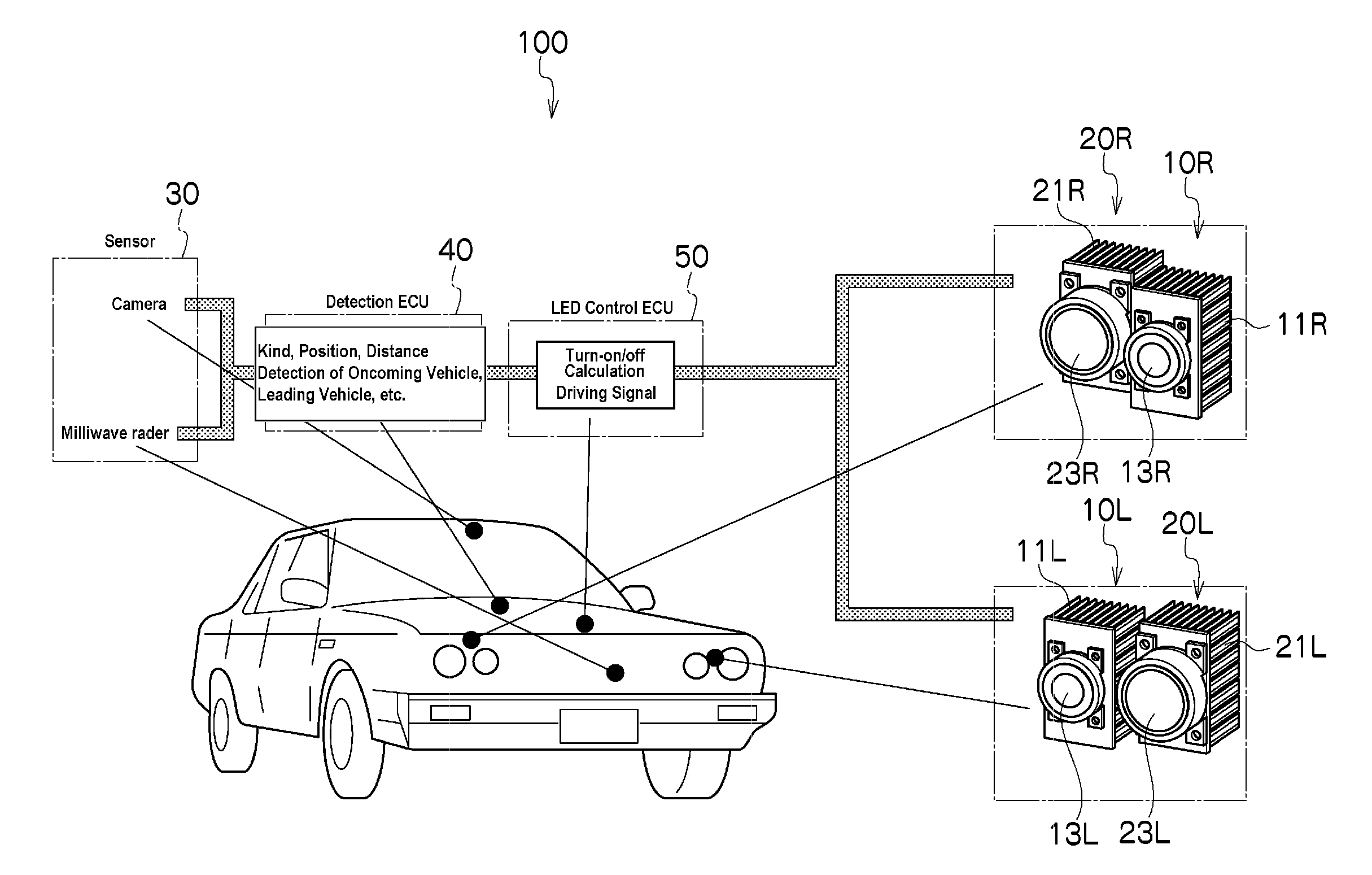
[0036]A vehicle light distribution control system 100 can be applied to a vehicle headlamp. As shown in FIG. 3, the vehicle light distribution control system 100 can include a pair of optical units disposed, for example, in a right front portion of a vehicle body. The optical unit can include a first nearby illumination unit 10R and a first farther illumination unit 20R. In addition, the vehicle light distribution control system 100 can include a pair of optical units disposed in a left front portion of a vehicle body. The optical unit can include a second nearby illumination unit 10L and a second farther illumination unit 20L. Furthermore, the vehicle light distribution control system 100 can include a sensor 30, a detection ECU 40, and an...


PUM


Abstract

A vehicle light can form a synthetic light distribution pattern with an area where a surrounding vehicle exists being made darker than an area(s) surrounding that area. The synthetic light distribution pattern can allow a sufficient illumination range and a center light intensity required for a running beam to be compatible. The vehicle light can also form a light distribution pattern with only an area where a farther surrounding vehicle exists is made dark. The vehicle light can form the light distribution pattern by overlaying a plurality of first nearby illumination areas, a plurality of first farther illumination areas, a plurality of second nearby illumination areas, and a plurality of second farther illumination areas with the respective illumination areas being divided in a horizontal direction and individually controlled in terms of light intensity so that respective vertical division lines of the illumination areas appear in predetermined order in the horizontal direction.

Description

[0001]This application claims the priority benefit under 35 U.S.C. §119 of Japanese Patent Application No. 2010-070047 filed on Mar. 25, 2010, which is hereby incorporated in its entirety by reference.TECHNICAL FIELD[0002]The presently disclosed subject matter relates to a vehicle light and a method for controlling light distribution of a vehicle light, and in particular, to a vehicle light that can utilize a plurality of LED light sources and a method for controlling light distribution of such a vehicle light.BACKGROUND ART[0003]Conventional vehicle lights capable of forming a specific light distribution pattern have been proposed in which the specific light distribution pattern can have a darker area where a surrounding vehicle exists in order to prevent glare light from reaching the surrounding vehicles, such as oncoming vehicles, leading vehicles and the like (see, for example, Japanese Patent Application Laid-Open No. 2009-218155 and its corresponding U.S. Patent Application Pu...

Claims


Application Information

Patent Timeline
Patent Type & Authority Patents(United States)
IPC IPC(8): B60Q1/00F21V1/00
CPCB60Q1/143F21S48/1747F21S48/1154B60Q2300/056B60Q2300/42B60Q2300/41F21S41/143F21S41/151F21S41/663
Inventor NAKAYA, YOSHIAKIMATSUZAKI, MAKIO
Owner STANLEY ELECTRIC CO LTD
Why Eureka
Try Eureka