Illuminating device

a technology of illumination device and light guide body, which is applied in the direction of lighting and heating apparatus, semiconductor devices for light sources, and light support devices. it can solve the problems and affecting the uniformity of light from the entire area of the light radiation surface of the light guide body. achieve the effect of reducing the size of the light emitting device, reducing the width of the light guid

Active Publication Date: 2018-10-02
TOYODA GOSEI CO LTD
View PDF7 Cites 0 Cited by
  • Summary
  • Abstract
  • Description
  • Claims
  • Application Information

AI Technical Summary

Benefits of technology

[0007]The disclosure provides an illuminating device that can be reduced in size, and can uniformly emit light from the entire area of its light radiation surface.
[0024]With the above arrangement, the emitted light of the light source is more likely to be incident on the inner surface of the lens and refracted as the light approaches the front end of the lens, so that the light can be radiated from the light radiation surface of the lens, farther on the front side of the illuminating device. Thus, the illuminating device can illuminate a wide area along the longitudinal direction of the case and the lens.

Problems solved by technology

With the technology of JP 2007-185980 A, the width of the light guide body is increased by that of the light emitting portion formed in the region located on one side of the light source; therefore, reduction of the size of the light emitting device may be impeded.
Therefore, it may be difficult to evenly or uniformly emit light from the entire area of a light radiation surface of the light guide body.
Thus, it is still difficult to uniformly emit light from the entire area of the light radiation surface of the light guide body, even with the use of the diffusing material.

Method used


Image

  • Illuminating device
  • Illuminating device
  • Illuminating device

Examples


Embodiment Construction

[0036]In the following, one embodiment of the disclosure will be described with reference to the drawings. In each of the drawings, constituent members are schematically illustrated with some dimensions, shapes and positions of the members exaggerated, for the sake of easy understanding of the description, and the dimensions, shapes and positions of the illustrated constituent members do not necessarily conform with those of the actual members.

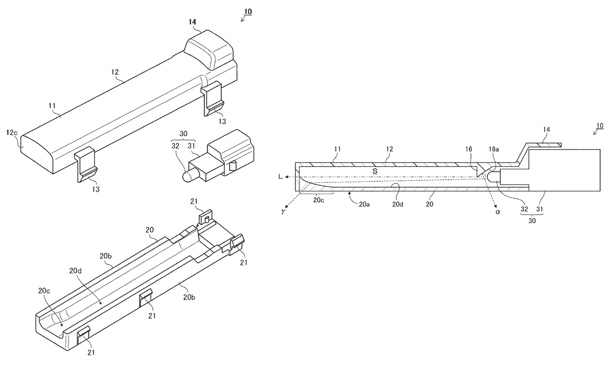
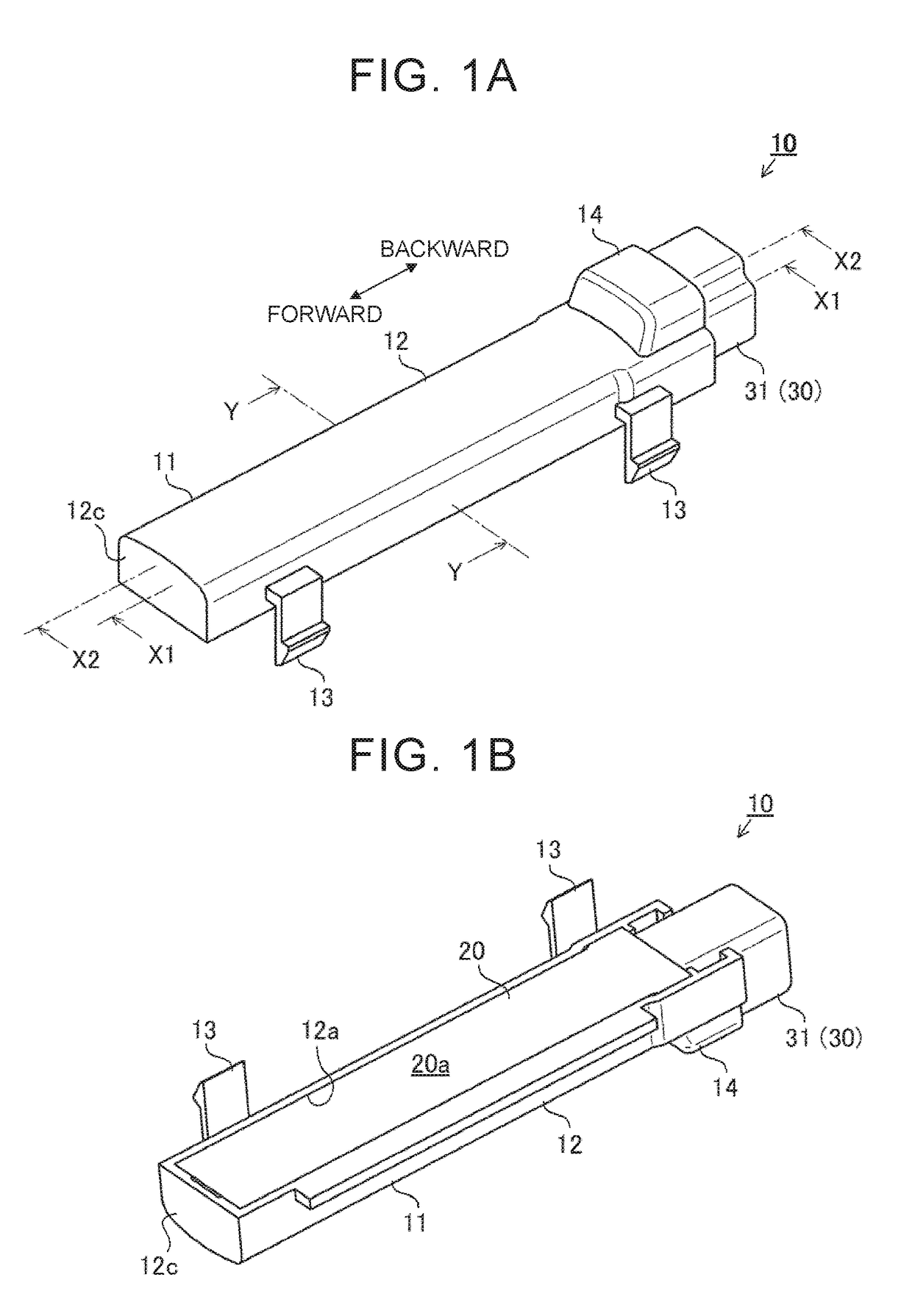
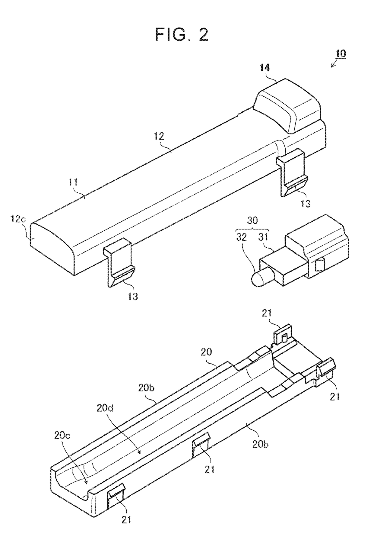
[0037]As shown in FIG. 1A through FIG. 8, an illuminating device 10 of this embodiment includes a case 11 (main body 12, opening 12a, inner bottom surface 12b, front end wall portion 12c, exterior mounting portions 13, light-source mounting portion 14, light reflecting portions 15, 16, light reflecting surfaces 15a, 16a), a lens 20 (light radiation surface 20a, side wall portions 20b, front end portion 20c, inner bottom surface 20d, inner corner portions 20e, engaging projections 21), a light source assembly 30 (connector portion 31, light sou...


PUM


Abstract

An illuminating device includes a light source having a light-source optical axis, a lens that is located substantially parallel to the light-source optical axis such that a surface of the lens faces the light-source optical axis, the lens extending to a position rearward of the light source in a direction of the light-source optical axis, and a light reflecting portion located so as to be opposed to a front side of the light source, the light reflecting portion being adapted to reflect emitted light of the light source obliquely rearward of the light source, and reflect the emitted light toward the lens.

Description

INCORPORATION BY REFERENCE[0001]The disclosure of Japanese Patent Application No. 2016-062886 filed on Mar. 25, 2016 including the specification, drawings and abstract is incorporated herein by reference in its entirety.BACKGROUND[0002]1. Technical Field[0003]The disclosure relates to an illuminating device.[0004]2. Description of Related Art[0005]A light emitting device disclosed in Japanese Patent Application Publication No. 2007-185980 (JP 2007-185980 A) includes a light source, and a light guide body into which light is introduced from the light source, and the light source is housed in a housing portion formed on the upper surface side of the light guide body. In the light emitting device, a light emitting portion is formed which extends from a region located obliquely forward of the light source, to a region located on one side of the light source, and a region located obliquely rearward of the light source, in a portion of the lower surface of the light guide body which is no...

Claims


Application Information

Patent Timeline
Patent Type & Authority Patents(United States)
IPC IPC(8): F21V7/04F21V21/08F21V13/04F21V5/04F21V7/00
CPCF21V13/04F21V5/04F21V21/08F21V7/04F21V7/0025F21V7/0066F21V15/01F21Y2115/10
Inventor UMEDA, YUKIHIKOENDO, KOICHIRO
Owner TOYODA GOSEI CO LTD
Why Eureka
Try Eureka