Image capture device

a technology of image capture and camera, which is applied in the direction of counting objects on conveyors, instruments, television systems, etc., can solve the problems of difficult assembly, limited incorporation in other equipment, and the device cannot be easily made compa

Inactive Publication Date: 2009-11-10
FUJITSU LTD +1
View PDF6 Cites 1 Cited by
  • Summary
  • Abstract
  • Description
  • Claims
  • Application Information

AI Technical Summary

Benefits of technology

[0011]Hence an object of the invention is to provide an image capture device which has a small-size configuration, and performs spread illumination of a subject when performing image capture, and which can easily be assembled.
[0012]A further object of the invention is to provide an image capture device which has a small-size configuration, provides broad illumination of a subject to perform image capture, and for which the rate of occurrence of defect products is reduced.
[0013]Still a further object of the invention is to provide an image capture device which has a small-size configuration, provides broad illumination of a subject to perform image capture, and prevents the intrusion of unnecessary light into the image capture unit.
[0032]In this invention, a slit is provided at the lower end of the hood, so that a visible light filter can be installed in the hood, the visible light filter can be fixed to the outer case to eliminate a bonding process, and the occurrence of a gap between the hood and the visible light filter due to a spring action of the slit upon assembly can be prevented. Hence intrusion of light other than light irradiating the image capture range from a gap into the optical unit 34 can be prevented, external light can be blocked, and capture of distinct images is possible.

Problems solved by technology

In this image capture device of the prior art, as stated above, the point-light source elements are positioned at a distance, so that the device cannot easily be made compact, and there are limits to incorporation in other equipment.
Further, greater compactness results in difficulty of assembly, and the rate of occurrence of defects is high.
For these reasons, it has been difficult to realize an image capture device which is small in size and inexpensive.

Method used


Image

  • Image capture device
  • Image capture device
  • Image capture device

Examples


Embodiment Construction

[0048]Below, embodiments of the invention are explained in the order of the configuration of an image capture device, an illumination mechanism, a hood configuration, and other embodiments.

[0049]Image Capture Device

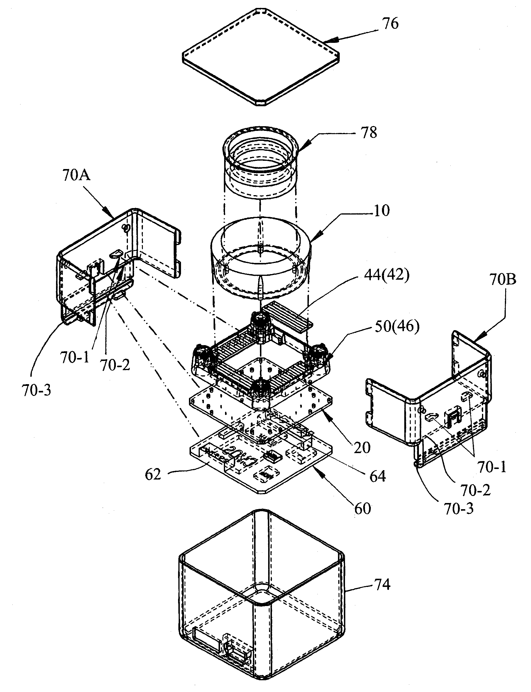
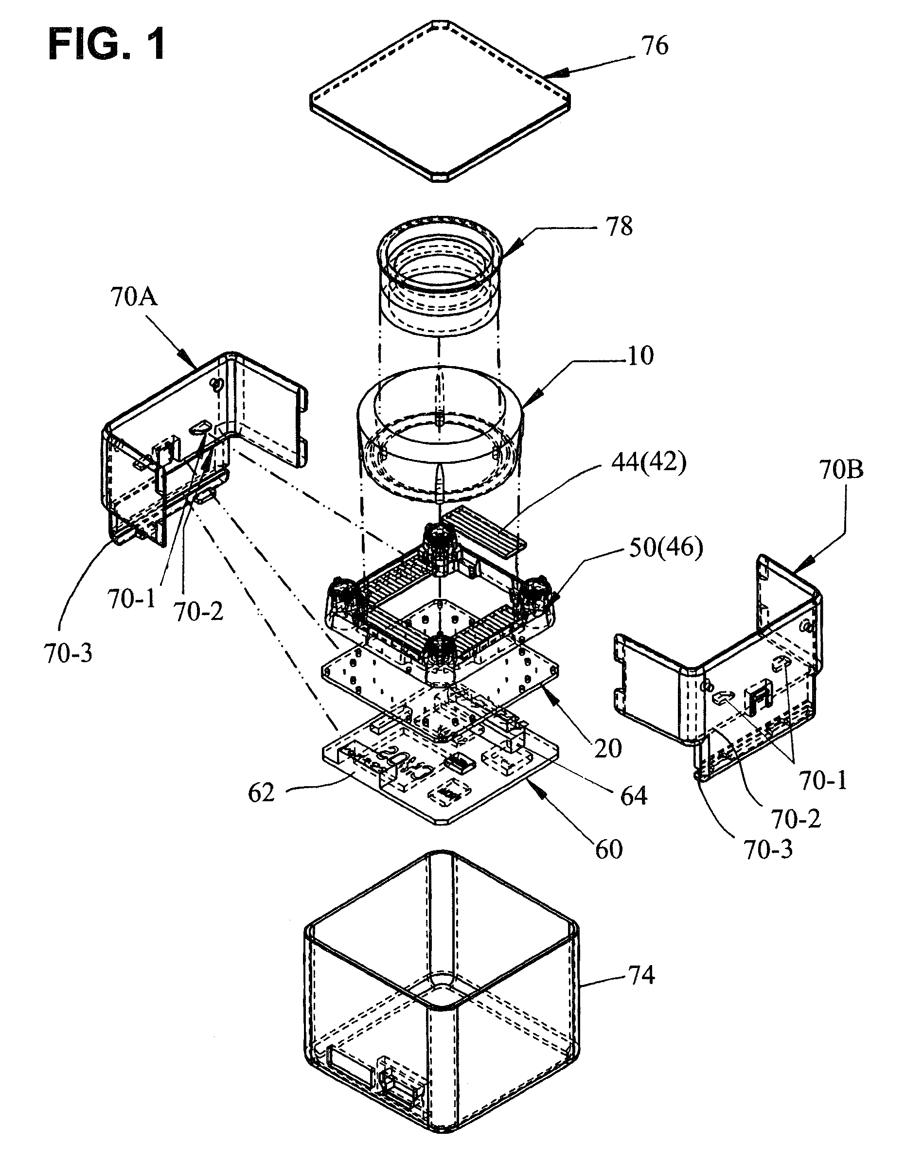
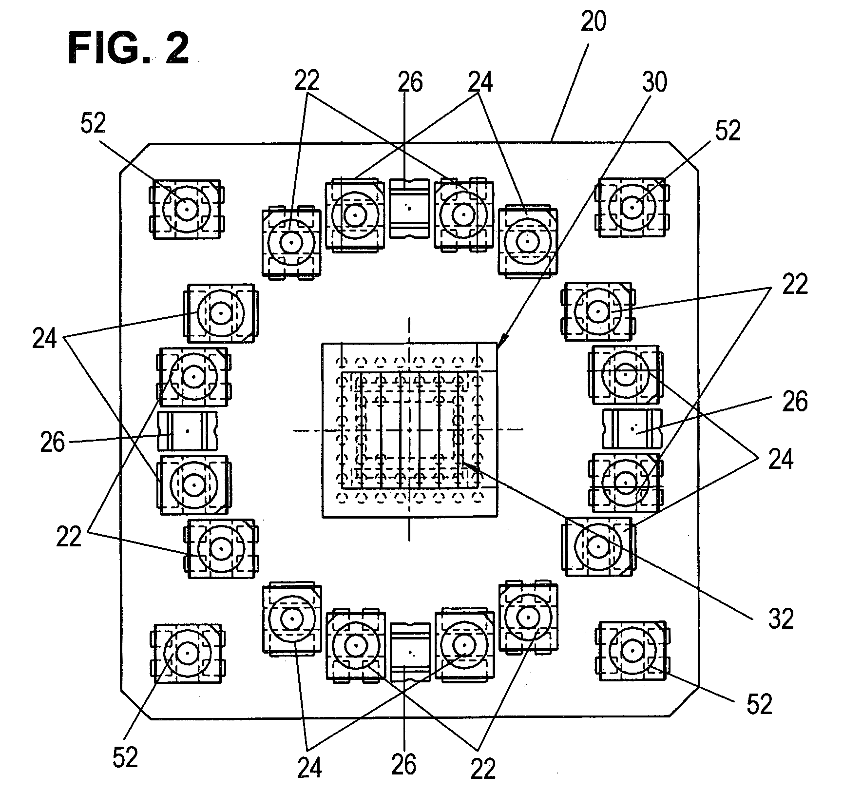
[0050]FIG. 1 is an exploded configuration diagram of the image capture device of one embodiment of the invention, FIG. 2 is a top view of the board in FIG. 1, and FIG. 3 is a cross-sectional view of the image capture device of FIG. 1.

[0051]As shown in FIG. 1, a camera board 20 and control board 60 are provided. As shown in FIG. 2, a CMOS image sensor or other image sensor 30 and a polarizing plate 32 are provided at the center of the camera board 20. On the periphery of the image sensor 30 on the camera board 20 are mounted a plurality of light-emitting elements 22, 24 and a plurality of light-receiving elements 26.

[0052]That is, an image sensor 30 is mounted at the center of the camera board 20, and a polarizing plate 32 is affixed thereupon. A plurality of light-emittin...


PUM


Abstract

An image capture device, which illuminates a subject and receives light reflected from the subject to capture an image of the subject, is provided to achieve a small-size configuration and easy assembly. A plurality of light-emitting elements are mounted in positions on the periphery of an image sensor, and a light-guiding member guides light from the plurality of light-emitting elements to the image capture range for illumination. And protrusions of the light-guiding member are pressed by the lower end of a hood which blocks light from outside the image capture range, and the hood upper end is pressed by a filter. Slits are provided in the hood lower end. Even in assembly where a visible light filter is installed on the hood and fixed to an outer case, the occurrence of gaps between the hood and the visible light filter can be prevented through the spring action of the slits.

Description

CROSS-REFERENCE TO RELATED APPLICATIONS[0001]This application is based upon and claims the benefit of priority from the prior Japanese Patent Application No. 2007-77063, filed on Mar. 23, 2007, the entire contents of which are incorporated herein by reference.BACKGROUND OF THE INVENTION[0002]1. Field of the Invention[0003]This invention relates to an image capture device which guides light from a light-emitting element to a subject, to irradiate the subject and capture an image, and in particular relates to an image capture device which is compact and easily assembled.[0004]2. Description of the Related Art[0005]Image capture devices which irradiate a subject with uniform light and capture an image of a prescribed range of the subject are in wide use. Distinct captured images are particularly demanded in image processing systems which use images captured by such image capture devices for image processing.[0006]For example, with advances in biometrics technology in recent years, vari...

Claims


Application Information

Patent Timeline
Patent Type & Authority Patents(United States)
IPC IPC(8): G03B15/03H04N5/222
CPCG06K9/00033H01L31/0232H01L31/0203G06V40/1312H04N23/00H04N23/75
Inventor YOSHIZU, YOSHIOTANAKA, HIROYUKI
Owner FUJITSU LTD
Why Eureka
Try Eureka