Electronic apparatus and illuminating device

a technology of illuminating device and electronic equipment, which is applied in the direction of lighting and heating equipment, instruments, diffusing elements, etc., can solve the problems of inability to achieve impressive illumination, light emission, and leds that cannot illuminate uniformly over a wide range, and achieve the effect of sufficient brightness

Inactive Publication Date: 2008-06-19
FUJITSU LTD
View PDF3 Cites 0 Cited by
  • Summary
  • Abstract
  • Description
  • Claims
  • Application Information

AI Technical Summary

Benefits of technology

[0006]It is accordingly an object of the present invention to provide an electronic apparatus and an illuminating device, allowing an optical member to illuminate over a wide range with a sufficient brightness.

Problems solved by technology

Light emitted from the LED leaks at the surface of the mobile phone terminal.
The LEDs cannot illuminate uniformly over a wide range.
Impressive illumination cannot thus be obtained.

Method used


Image

  • Electronic apparatus and illuminating device
  • Electronic apparatus and illuminating device
  • Electronic apparatus and illuminating device

Examples


Embodiment Construction

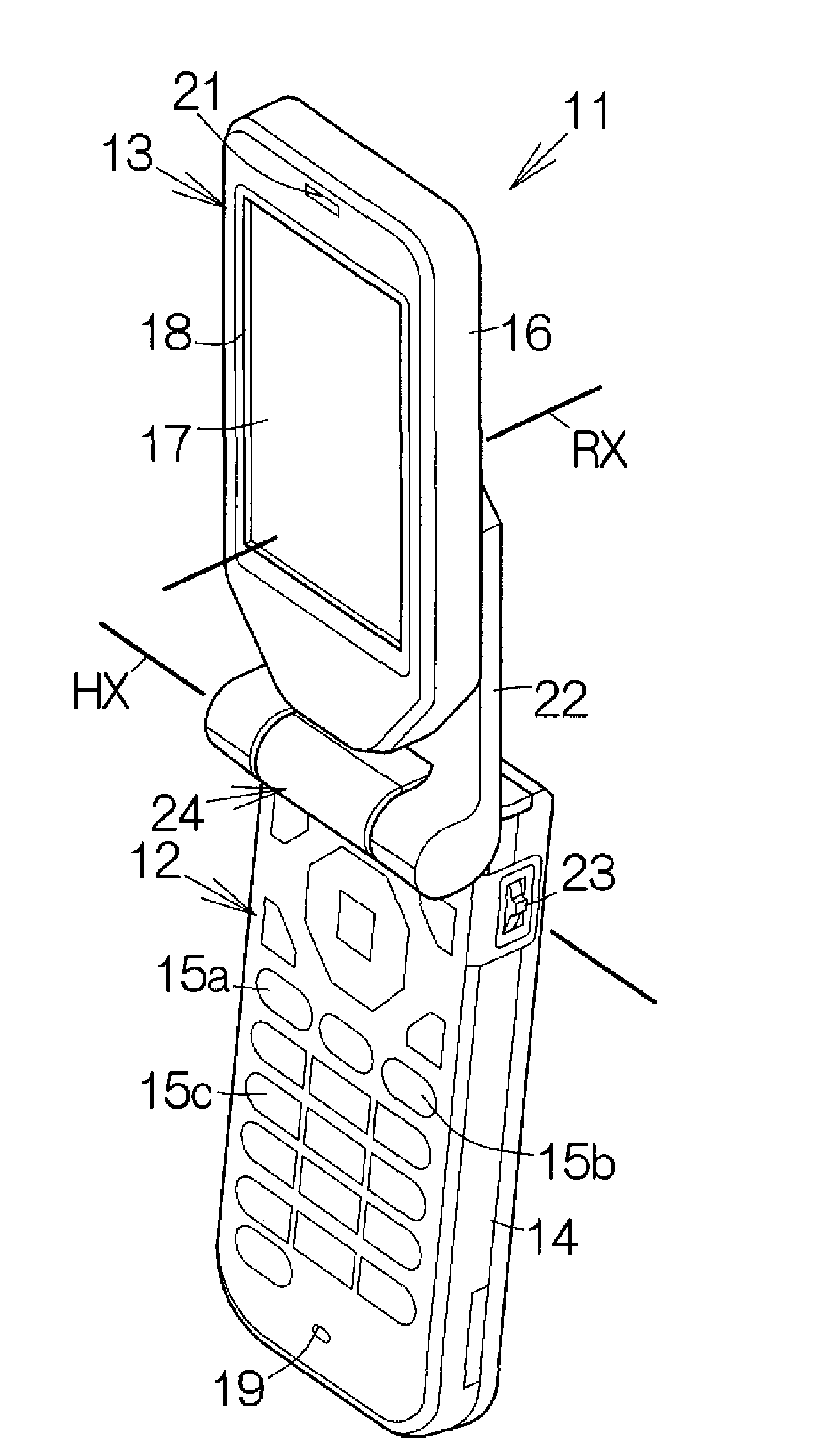
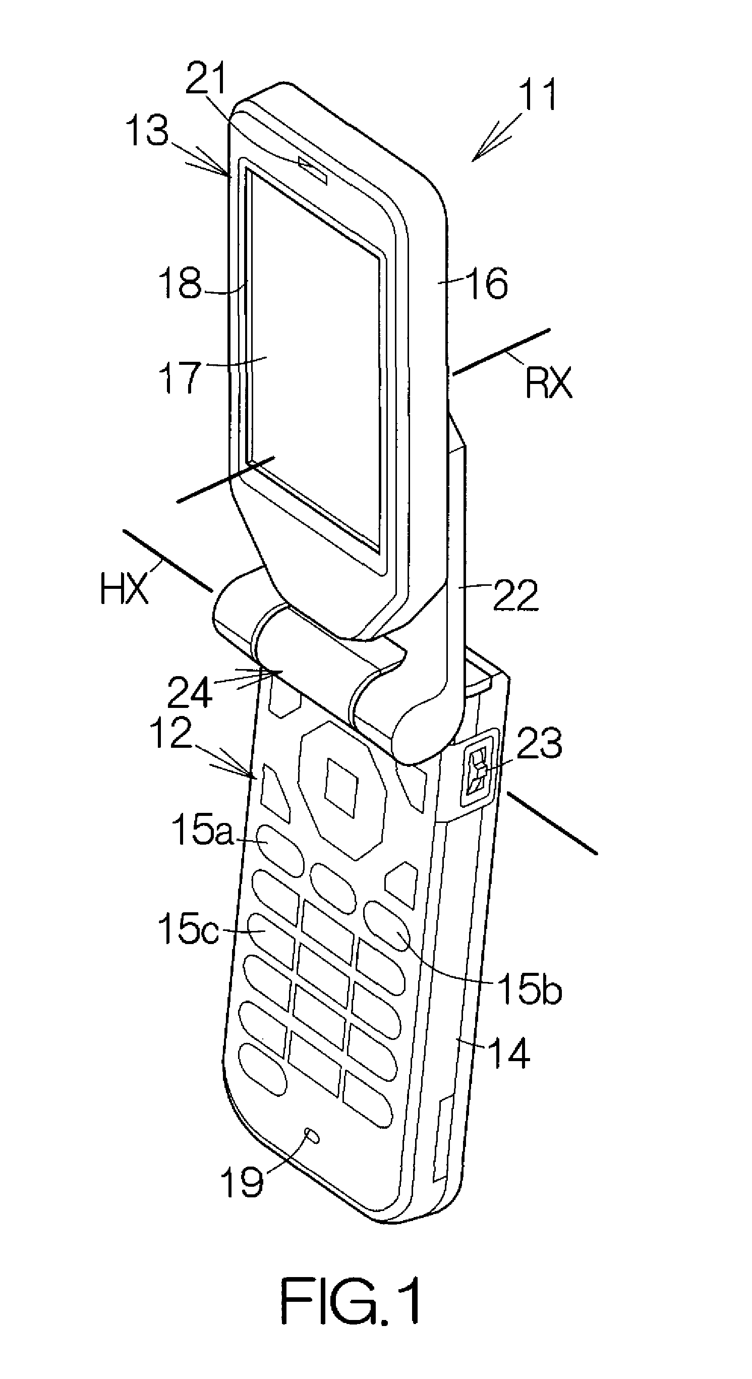
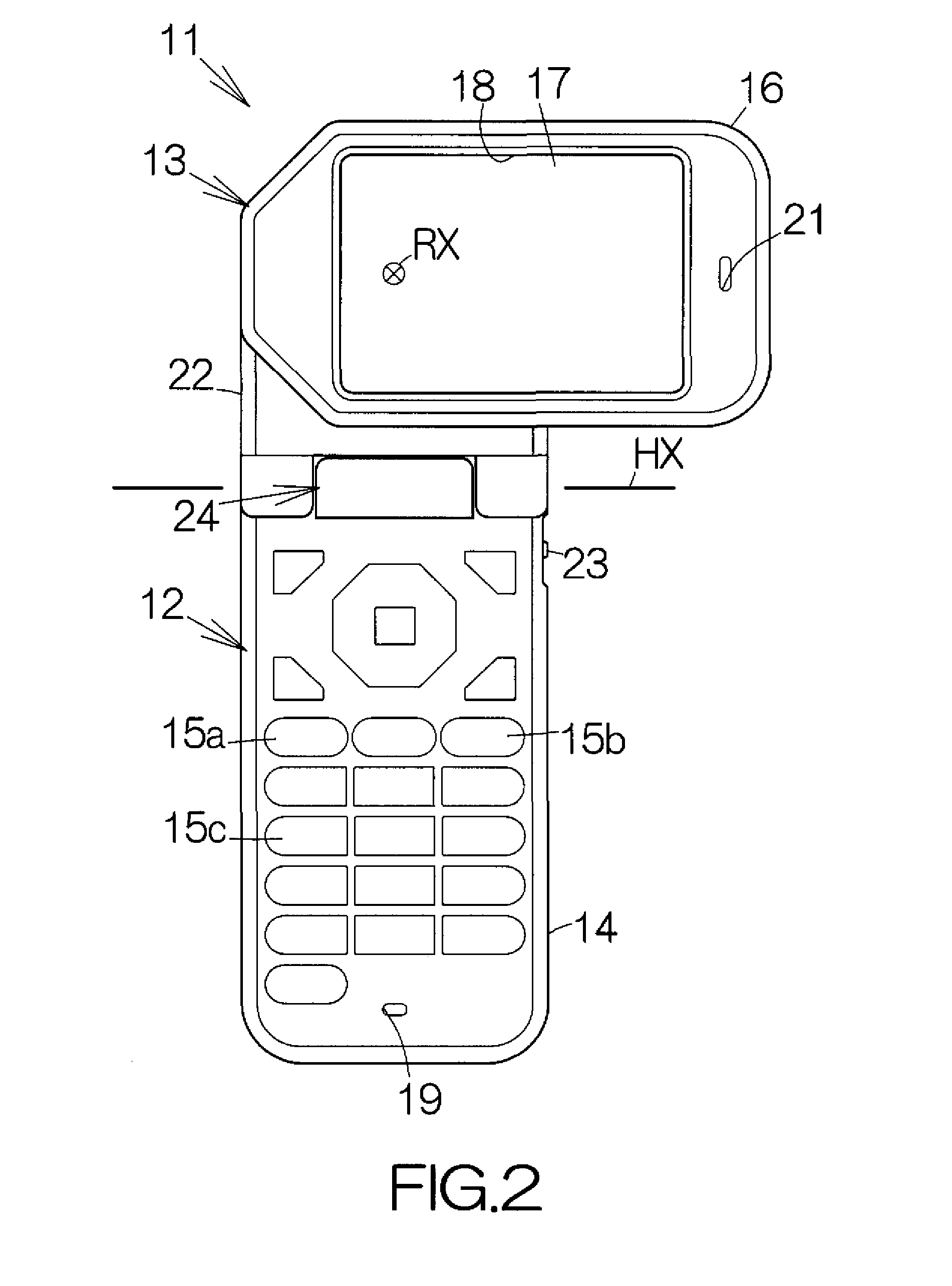
[0028]FIG. 1 schematically illustrates a cellular or mobile phone terminal 11 of the clamshell type as an example of an electronic apparatus according to an embodiment of the present invention. The mobile phone terminal 11 includes a main apparatus 12 and a display unit 13. The main apparatus 12 includes a main body enclosure 14 serving as a first enclosure. A printed circuit board, not shown, is incorporated in the main body enclosure 14. Processing circuits, such as a central processing unit (CPU) and a memory, are mounted on the printed circuit board in a conventional manner. Keypads, such as an on-hook keypad 15a, an off-hook keypad 15b, numeric keypads 15c, and the like, are embedded in the flat front surface of the main apparatus 12. The CPU executes various processing in response to the manipulation of the keypads. The main body enclosure 14 may be molded from a reinforced resin material such as acrylonitrile butadiene styrene (ABS), for example.

[0029]The display unit 13 incl...


PUM


Abstract

A light emitting element is mounted on the surface of a board. The light emitting element emits light. The light passes through a translucent optical member. The light enters the translucent optical member through a incident surface. The lines of protrusions make the incident surface jagged. The jagged surface resulting from the protrusions enables diffusion of the light entering through the incident surface. The light spreads along the surface of the board. Simultaneously, the emitted light is partly reflected on the incident surface. The reflected light is reflected on a reflecting surface placed behind the light emitting element. The reflected light then enters the translucent optical member. The translucent optical member is thus allowed to illuminate over a wide range with a sufficient brightness. An impressive illumination can be realized.

Description

BACKGROUND OF THE INVENTION[0001]1. Field of the Invention[0002]The present invention relates to an electronic apparatus such as a cellular or mobile phone terminal. In particular, the present invention relates to an electronic apparatus including a light emitting element incorporated in an enclosure.[0003]2. Description of the Prior Art[0004]A light emitting element such as a light-emitting diode (LED) is incorporated in a mobile phone terminal. Light emitted from the LED leaks at the surface of the mobile phone terminal. Light blinks in response to the receipt of a call, in synchronization with music, and the like, for example.[0005]The light emitted from the LED has a high directivity. The LED cannot illuminate over a wide range. In the case where two or more LEDs are utilized, each LED makes a spot. The LEDs cannot illuminate uniformly over a wide range. Impressive illumination cannot thus be obtained.SUMMARY OF THE INVENTION[0006]It is accordingly an object of the present inven...

Claims


Application Information

Patent Timeline
Patent Type & Authority Applications(United States)
IPC IPC(8): F21V7/00F21V1/00
CPCF21V33/0052H04M1/0214H04M1/236H04M1/22H04M1/0227
Inventor ISHIKAWA, TAKEHISAKAJIWARA, YOSHIFUMISAKASHITA, HIROAKIMATSUMOTO, YOSHIYAMURAYAMA, KAZUNORIYAMAMOTO, ATSUKOTANAKA, HIROYUKI
Owner FUJITSU LTD
Why Eureka
Try Eureka