Single-ended signaling with parallel transmit and return current flow

a transmit and return current and single-ended technology, applied in the field ofsignal, can solve the problems of reducing the signaling margin, preventing the adoption of two conductors per signal, and preventing the introduction of uniform impedances,

Active Publication Date: 2013-08-20
RAMBUS INC
View PDF11 Cites 5 Cited by
  • Summary
  • Abstract
  • Description
  • Claims
  • Application Information

AI Technical Summary

Problems solved by technology

Despite the performance gains available through differential signaling, the cost of two conductors per signal continues to impede its adoption in a number of chip-to-chip signaling applications, particularly those that require relatively wide data paths (e.g., between a memory controller and memory devices).
Another challenge presented within the single-ended signaling system is the data-dependent curr

Method used


Image

  • Single-ended signaling with parallel transmit and return current flow
  • Single-ended signaling with parallel transmit and return current flow
  • Single-ended signaling with parallel transmit and return current flow

Examples


Embodiment Construction

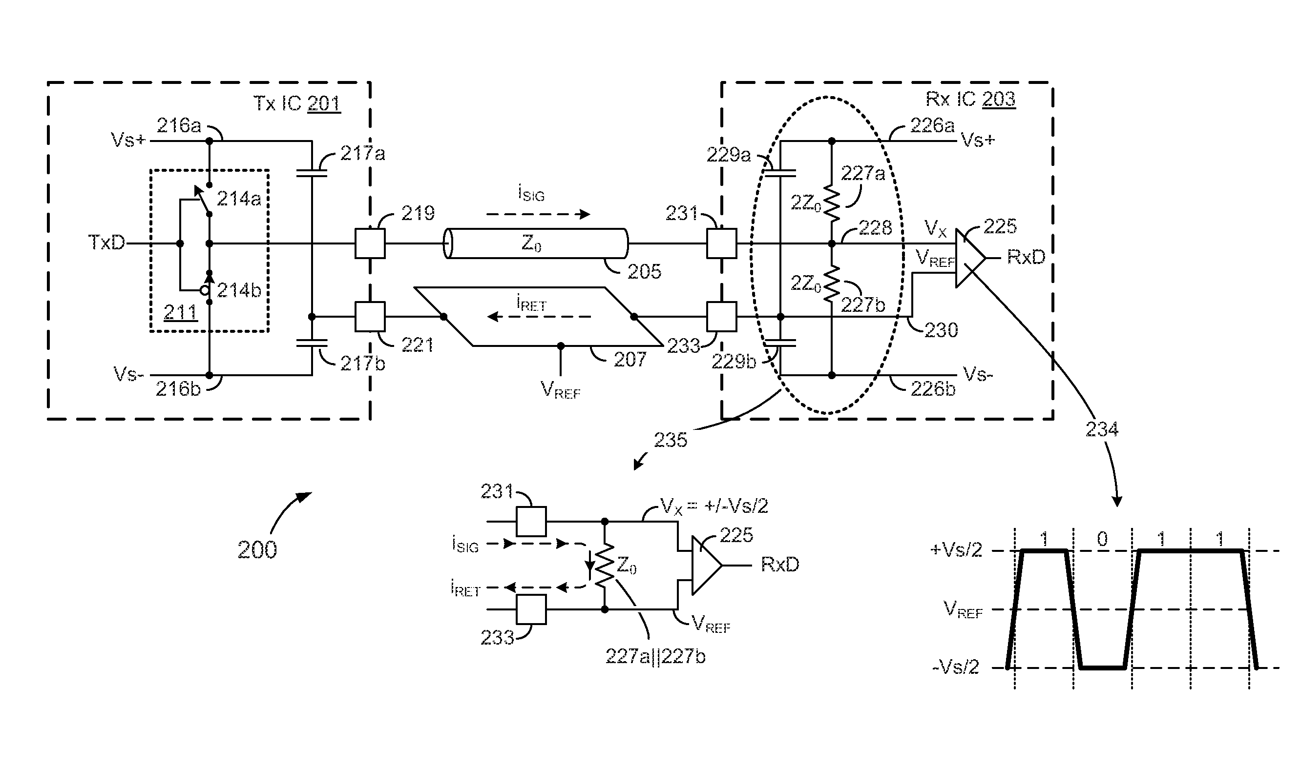
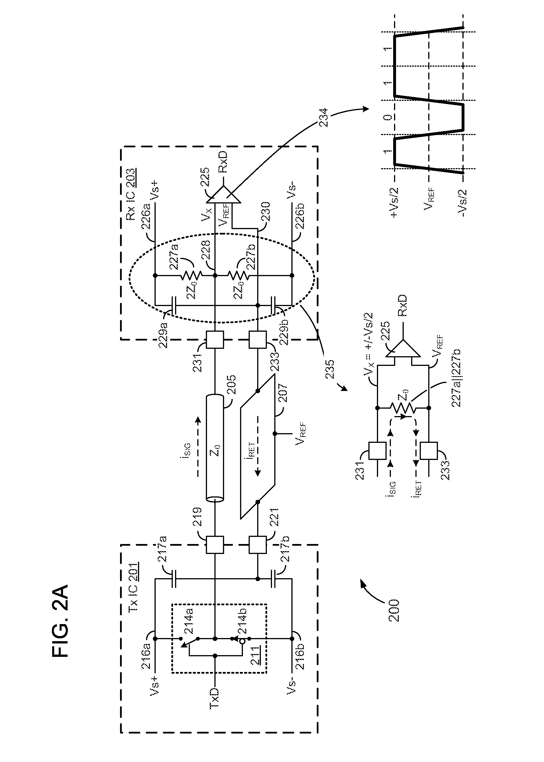
[0016]A single-ended signaling system in which transmitted and returned signal currents are enabled to flow substantially parallel to one another and thereby maintain a substantially uniform impedance along the length of a single-ended signal conductor is presented in various embodiments. In one embodiment, a reference plane is disposed substantially parallel to a single-ended signaling conductor and coupled to the signaling conductor within a signal-receiving IC and coupled to signaling supply voltage nodes within a signal-transmitting IC. By this arrangement, an AC current flowing to (or from) the receiving IC via the signaling conductor is conducted to the reference plane, thereby enabling a matching AC current to flow back to (or back from) the transmitting IC along a single path that is substantially parallel to the signal conductor.

[0017]In a more specific embodiment, the reference plane is coupled to a reference voltage input of a signal-receiving circuit within the receiving...


PUM


Abstract

A single-ended signaling system in which transmitted and returned signal currents are enabled to flow substantially parallel to one another and thereby maintain a substantially uniform impedance along the length of a single-ended signal conductor. A reference plane is disposed substantially parallel to a single-ended signaling conductor and coupled to the signaling conductor within a signal-receiving IC and to signaling supply voltage nodes within a signal-transmitting IC. By this arrangement, an signal current flowing to or from the receiving IC via the signaling conductor is conducted to the reference plane, thereby enabling a signal-return current to flow back to or back from the transmitting IC along a single path that is substantially parallel to the signal conductor.

Description

CROSS REFERENCE TO RELATED APPLICATIONS[0001]Pursuant to 35 U.S.C. §§365 and 371, this application is a United States National Stage Application that claims priority to International Application No. PCT / US2010 / 049164 filed Sep. 16, 2010, which claims priority to U.S. Provisional Patent Application No. 61 / 253,445 filed Oct. 20, 2009. Each of the above-identified patent applications is hereby incorporated by reference in its entirety.TECHNICAL FIELD[0002]The present invention relates generally to the field of electronic communications and more particularly to signaling between integrated circuit devices.BACKGROUND[0003]Despite the performance gains available through differential signaling, the cost of two conductors per signal continues to impede its adoption in a number of chip-to-chip signaling applications, particularly those that require relatively wide data paths (e.g., between a memory controller and memory devices). Instead, single-ended signaling continues to prevail in such a...

Claims


Application Information

Patent Timeline
IPC IPC(8): H03K19/0175
CPCH04L25/0278
Inventor CHANG, KUN-YUNG KENPOULTON, JOHN W.
Owner RAMBUS INC
Why Eureka
Try Eureka