Visual prosthesis with an improved electrode array adapted for foveal stimulation

a technology of electrode array and visual prosthesis, which is applied in the field of visual prosthesis and improved electrode array, can solve the problems of large prosthetic device, insufficient simulated vision, and inability to truly aid the visually impaired, and achieve the effect of maximizing the retinal response and more controlled light perception

Active Publication Date: 2013-11-19
CORTIGENT INC
View PDF12 Cites 0 Cited by
  • Summary
  • Abstract
  • Description
  • Claims
  • Application Information

AI Technical Summary

Benefits of technology

[0015]The present invention is an improved method of electrically stimulating percepts in a patient with a visual prosthesis, to induce a more controlled perception of light. In particular, the present invention is an improved electrode array to maximize retinal response. The array of the present invention is an array with a center section with no electrode, surrounded by a ring of small high density electrodes. Electrodes beyond to ring are gradually larger and more widely spaced. The array includes a center portion with no electrodes over the foveal pit, a high density of small electrodes surrounding the center portion, which gradually increase in both size and spatial pitch moving away from the fovea.

Problems solved by technology

While some of these early attempts met with some limited success, these early prosthetic devices were large, bulky and could not produce adequate simulated vision to truly aid the visually impaired.

Method used


Image

  • Visual prosthesis with an improved electrode array adapted for foveal stimulation
  • Visual prosthesis with an improved electrode array adapted for foveal stimulation
  • Visual prosthesis with an improved electrode array adapted for foveal stimulation

Examples


Embodiment Construction

[0022]The following description is of the best mode presently contemplated for carrying out the invention. This description is not to be taken in a limiting sense, but is made merely for the purpose of describing the general principles of the invention. The scope of the invention should be determined with reference to the claims.

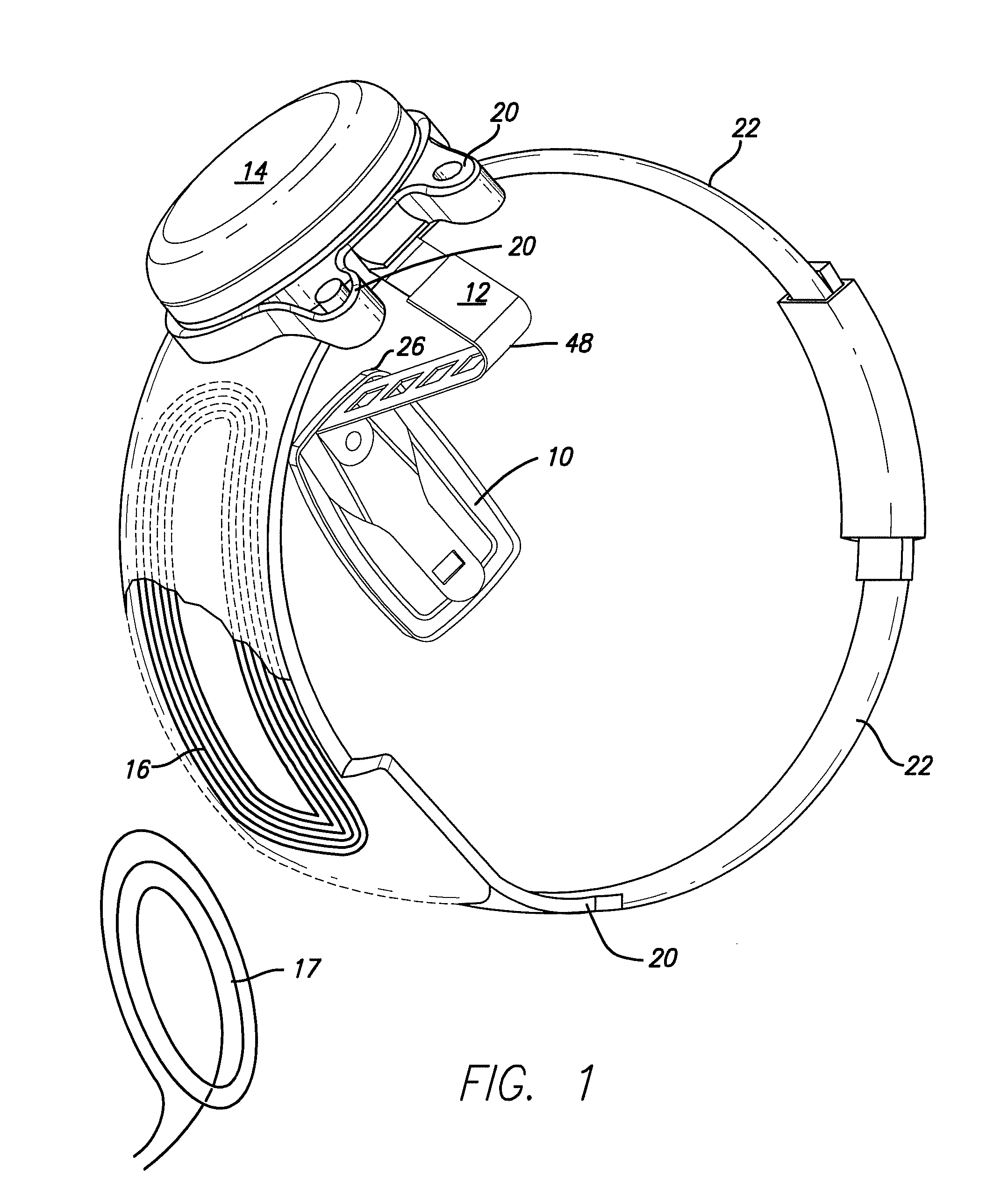
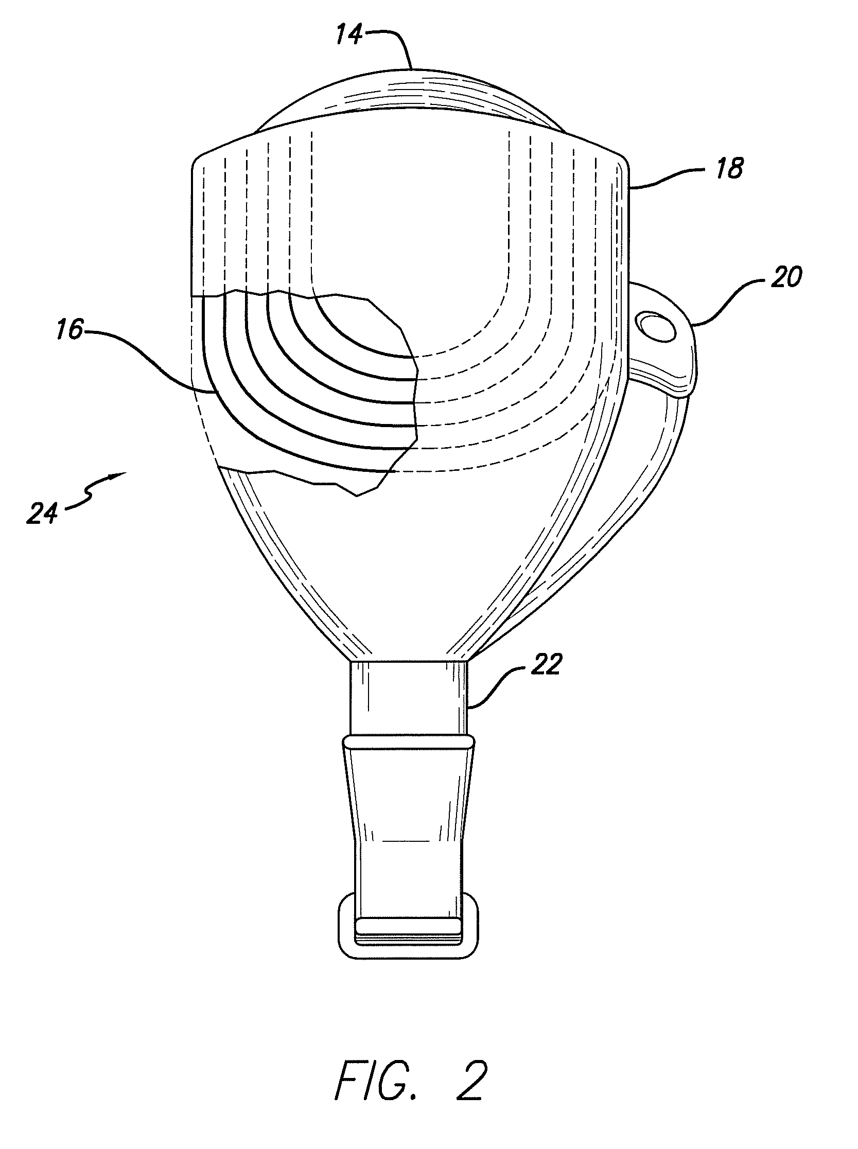
[0023]FIGS. 1 and 2 present the general structure of a visual prosthesis used in implementing the invention.

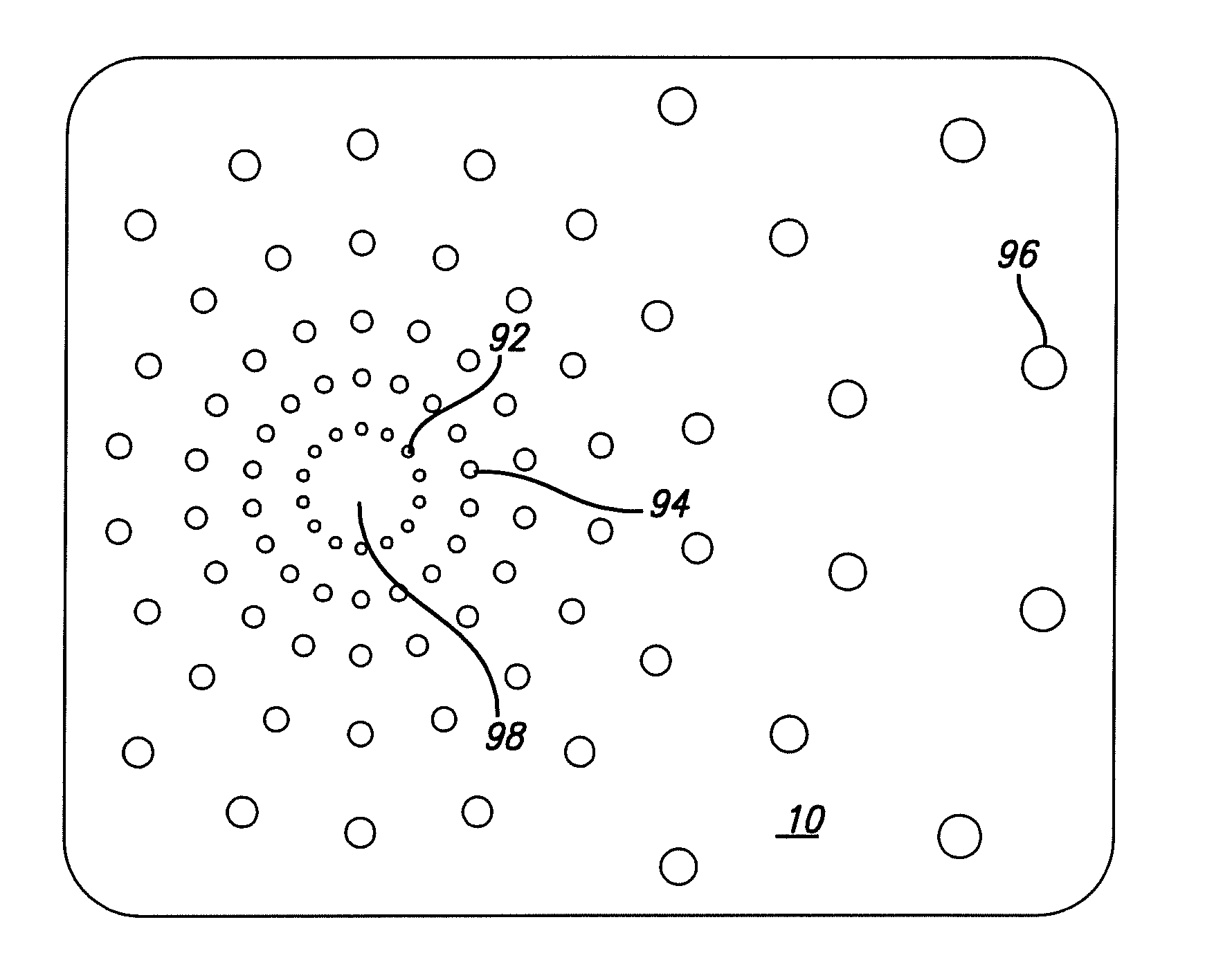
[0024]FIG. 1 shows a perspective view of the implanted portion of the preferred retinal prosthesis. A flexible circuit 1 includes a flexible circuit electrode array 10 which is mounted by a retinal tack (not shown) or similar means to the epiretinal surface. The flexible circuit electrode array 10 is electrically coupled by a flexible circuit cable 12, which pierces the sclera and is electrically coupled to an electronics package 14, external to the sclera.

[0025]The electronics package 14 is electrically coupled to a secondary inductive coil 16. Prefer...


PUM


Abstract

The present invention is an improved method of electrically stimulating percepts in a patient with a visual prosthesis, to induce a more controlled perception of light. In particular, the present invention is an improved electrode array to maximize retinal response. The array of the present invention is an array with a center section with no electrode, surrounded by a ring of small high density electrodes. Electrodes beyond to ring are gradually larger and more widely spaced.

Description

CROSS REFERENCE TO RELATED APPLICATIONS[0001]This application claims benefit of, and incorporates by reference, U.S. Provisional Patent Application 61 / 413,271, filed Nov. 12, 2010, for Method of Controlling the Temporal Dynamics of Percepts in a Visual Prosthesis. This application is related to an incorporates by reference, U.S. Pat. No. 7,149,585, for Variable Pitch Electrode Array, and U.S. Pat. No. 8,014,878, for Flexible Circuit Electrode Array.FIELD OF THE INVENTION[0002]The present invention is an improved method of electrically stimulating percepts in a patient with a visual prosthesis, to induce a more controlled perception of light. In particular, the present invention is an improved electrode array to maximize retinal response.BACKGROUND OF THE INVENTION[0003]In 1755 LeRoy passed the discharge of a Leyden jar through the orbit of a man who was blind from cataract and the patient saw “flames passing rapidly downwards.” Ever since, there has been a fascination with electrica...

Claims


Application Information

Patent Timeline
Patent Type & Authority Patents(United States)
IPC IPC(8): A61N1/05
CPCA61N1/0543A61N1/36046
Inventor GREENBERG, ROBERT J.AHUJA, ASHISH
Owner CORTIGENT INC
Why Eureka
Try Eureka