Pump assembly, in particular for helicopter lubrication

a technology for pumping chambers and helicopters, which is applied in the direction of engine lubrication, rotary or oscillating piston engines, and piston engine lubrication, etc. it can solve the problems of low volumetric efficiency, rapid wear and unreliability of the pump, and the pumping chamber rarely manages to fill completely. , to achieve the effect of simple and low cos

Active Publication Date: 2014-03-11
LEONARDO FINMECCANICA SPA
View PDF30 Cites 0 Cited by
  • Summary
  • Abstract
  • Description
  • Claims
  • Application Information

AI Technical Summary

Benefits of technology

[0006]It is an object of the present invention to provide a pump assembly, in particular for helicopter lubrication, designed to provide a simple, low-cost solution to the above drawbacks.

Problems solved by technology

In helicopter transmissions, rotation speeds are relatively high, so volumetric efficiency is low.
That is, the pumping chambers rarely manage to fill completely, because of the short length of time they remain connected to the intake section.
Moreover, excessive rotation speed may cause cavitation phenomena, resulting in rapid wear and unreliability of the pump.

Method used


Image

  • Pump assembly, in particular for helicopter lubrication
  • Pump assembly, in particular for helicopter lubrication
  • Pump assembly, in particular for helicopter lubrication

Examples


Embodiment Construction

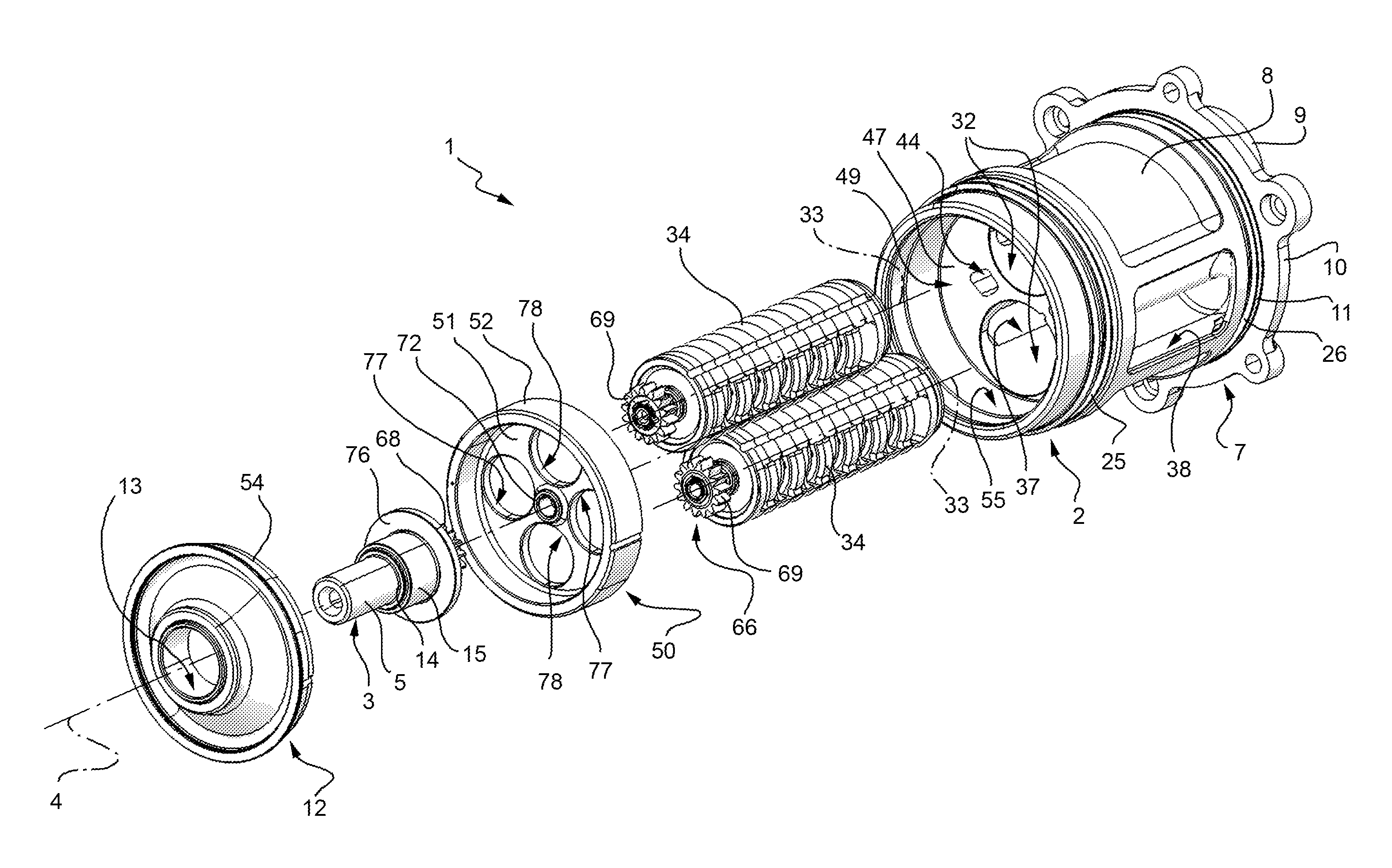
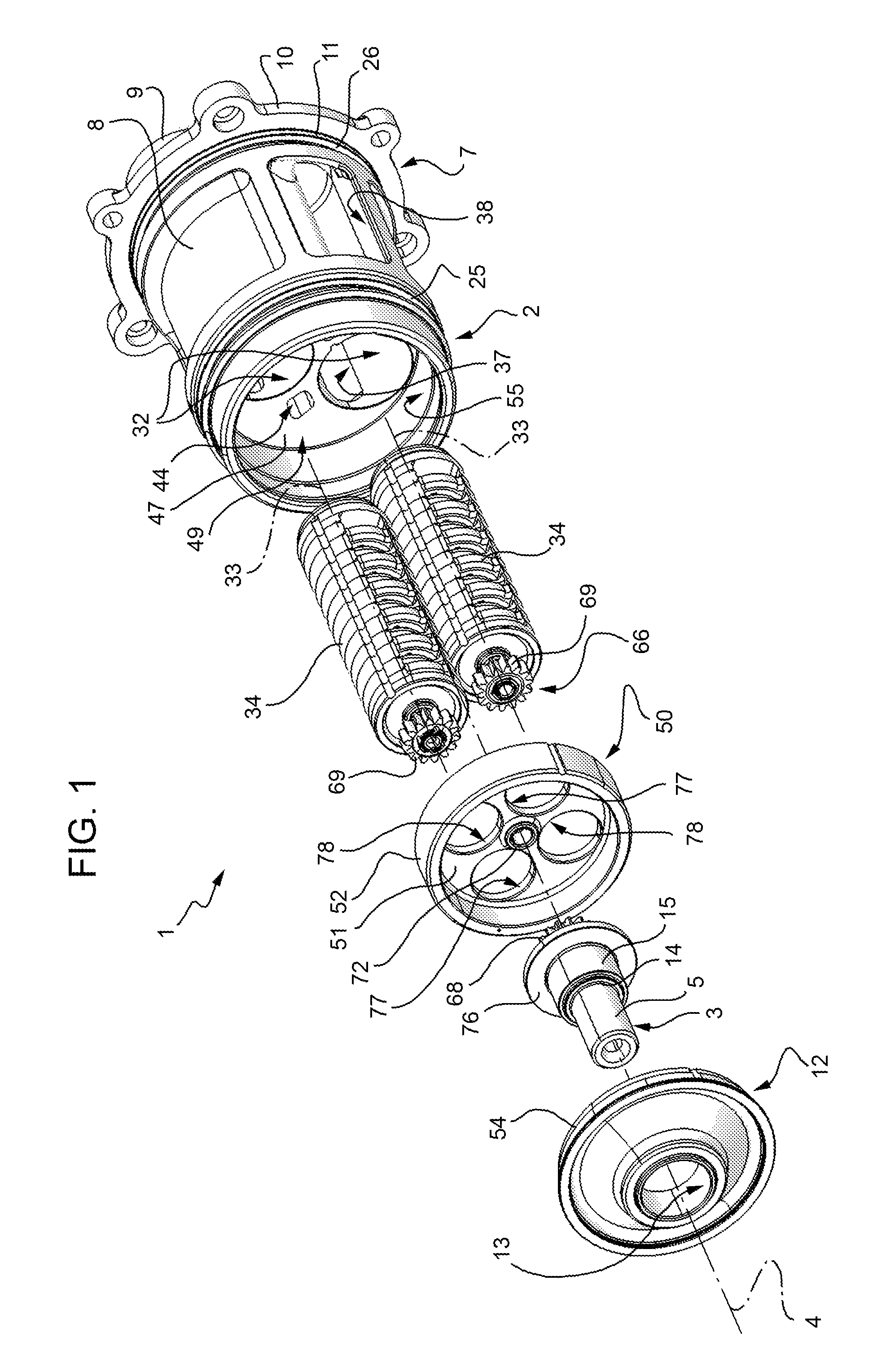
[0020]Number 1 in FIG. 1 indicates a pump assembly comprising a casing 2; and a drive shaft 3 extending along an axis 4 and terminating axially with a portion 5 outside casing 2.

[0021]Casing 2 comprises a hollow body 7 cast in one piece and in turn comprising a substantially cylindrical lateral wall 8, a rear wall 9 perpendicular to axis 4, and a flange 10 projecting from an end portion 11 of lateral wall 8. Casing 2 also comprises a plate 12 opposite rear wall 9, and which closes hollow body 7 axially, and has an axial hole 13 engaged by an intermediate portion 14 of shaft 3, with the interposition of a sliding bearing 15.

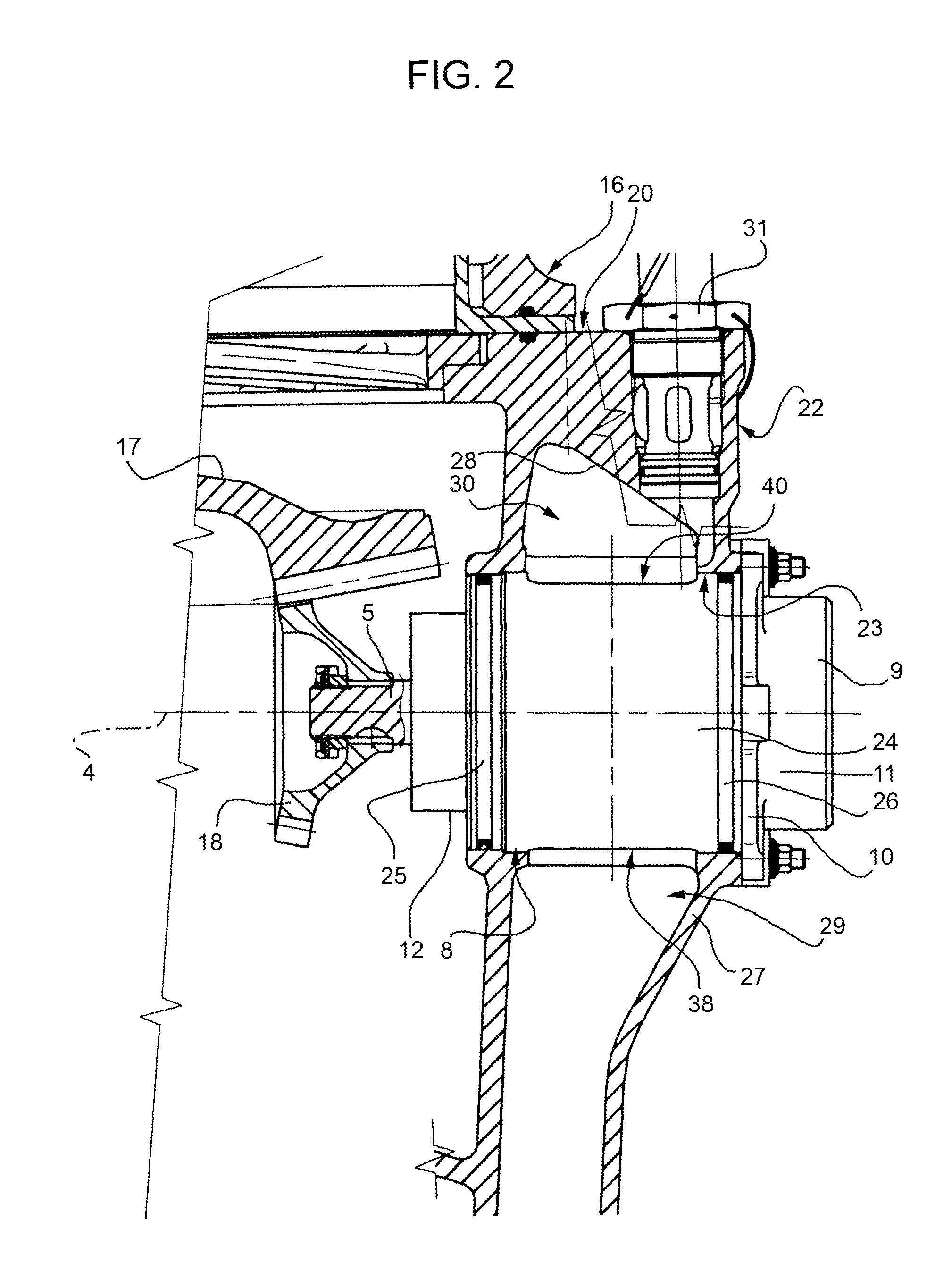
[0022]With reference to FIG. 2, pump assembly 1 may be used to advantage for lubricating a helicopter 16 (shown partly) comprising: a transmission 17 (shown partly) which rotates a gear 18 fitted in a fixed position to portion 5; and a box 20 (shown partly) enclosing transmission 17 and comprising a housing 22. Housing 22 has a substantially cylindrical seat 23 co...


PUM


Abstract

A pump assembly, in particular for lubrication in helicopters, has a casing, the lateral wall of which defines an intake port and a delivery port; and the casing houses two rotary pumps powered by a drive shaft via a motion-splitting transmission.

Description

CROSS REFERENCE TO RELATED APPLICATION[0001]This application claims the benefit of European Patent Application No. 10425326.5, filed on Oct. 6, 2010, which is hereby incorporated herein by reference in its entirety.BACKGROUND OF THE INVENTION[0002]As is known, commonly used helicopter transmission lubricating pumps have a drive shaft fitted with a gear that meshes with a gear in the transmission. The most common arrangement is what is known as a “cartridge”, i.e. the pump is housed partly inside a cylindrical seat coaxial with the drive shaft and formed in a housing, which has two sections on opposite sides of the pump and connected to the lubricating circuit intake and delivery pipes respectively.[0003]Since relatively little power is normally demanded of the pump, torque transmitted to the drive shaft is also relatively low, so the drive shaft can simply be supported by bushings, with no need for rolling bearings.[0004]The seat in the housing must be wide enough to permit passage ...

Claims


Application Information

Patent Timeline
Patent Type & Authority Patents(United States)
IPC IPC(8): F01C1/08
CPCF04C11/001F04C2210/14F04C15/0061F04C2/10F04C2/14F04C2/08F16N13/20
Inventor GABRIELLI, ANDREA
Owner LEONARDO FINMECCANICA SPA
Why Eureka
Try Eureka