
Advancing unit for positioning a current collector unit

a current collector and positioning technology, applied in the direction of power current collectors, electric vehicles, cranes, etc., can solve the problems of increasing friction, corrosion, blocking the movability of an advancing unit, and being exposed to unfavorable environmental and weather influences, so as to prolong the travelling range, effectively protecting from soiling and weather influences, and effectively protecting from icing and impairment of flexibility

Active Publication Date: 2017-03-07
CONDUCTIX WAMPFLER
View PDF26 Cites 1 Cited by
  • Summary
  • Abstract
  • Description
  • Claims
  • Application Information

AI Technical Summary

Benefits of technology

The patent describes a solution to protect the contact surfaces of guide elements in a cavity from environmental factors such as dirt, sand, moisture, snow, and foreign bodies. This is achieved by using a flexible band of variable length that is pulled or released based on need. No construction changes are required and the band is robust in operation. Additionally, a second flexible band can be added to cover a section of the open longitudinal side of the cavity not covered by the first band. This solution ensures a satisfactory functioning of the guides even in adverse environmental and weather conditions.

Problems solved by technology

Current collector systems of the type mentioned in the beginning are normally used in the open air and are therefore exposed to unfavorable environmental and weather influences.
This can lead to increased friction, corrosion, and, in the worst of cases, to a blocking of the movability of an advancing unit in the area of the running surfaces of guides.
A horizontal advancing unit is hereby particularly endangered, because its running surfaces lie approximately horizontal and thus are particularly susceptible for depositions of the previously mentioned type.

Method used


Image

  • Advancing unit for positioning a current collector unit
  • Advancing unit for positioning a current collector unit
  • Advancing unit for positioning a current collector unit

Examples


first embodiment

[0052]The pretensioning of the band 19 is already created in this case by the internal spring of the spring drum, so that other measures for the pretensioning of the band 19 can be omitted here. The spring drum can be fastened also on the extension roller carrier 20 instead of on the front end of the extension 6, and the other end of the band 19, instead, on the front end of the extension 6. The advantage of the embodiment is to be found in that it can also be used with an extension 6 alone, without a carriage 7, with the previously described kinematic coupling on the extension 6, whereas the first embodiment presupposes the presence of such a carriage 7 with the aforementioned kinematic coupling for the movement of the second end of the band 19, and for this reason, the configuration was described in detail in the preceding.

second embodiment

[0053]Also, the additional lateral cover of the rear part of the extension 6, which protrudes toward the rear over the fastening frame 5 in the retracted end position of FIG. 4, can readily be implemented with the second embodiment, in that a second band is provided on each double-T-track 14, and a second spring drum on the rear end.

[0054]In the depicted embodiment example, a number of additional features can be used in accordance with the invention that are not visible or are not shown in the figures. Among these is an arrangement of the band 19 that is slightly nonsymmetrical in the vertical direction, that is, it is displaced upward relative to the center of the double-T-track 14, by means of which a narrow slit remains on the underside between the double-T-track 14 and the band 19, through which condensation water or seepage water can run downward. Moreover, the extension 6 can be provided on its upper side with a cover (not shown), which, similar to the bridge 25, lies on the u...


PUM


Abstract

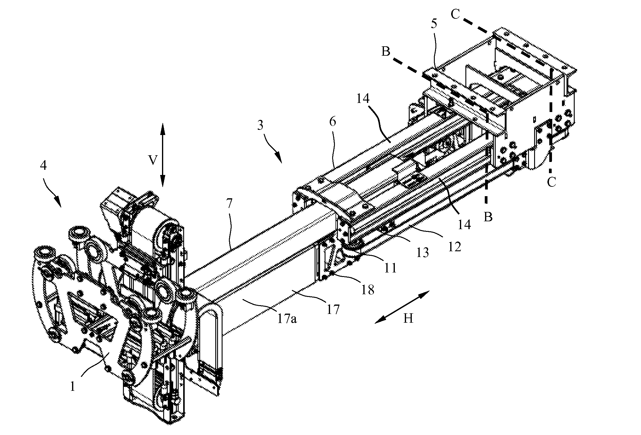
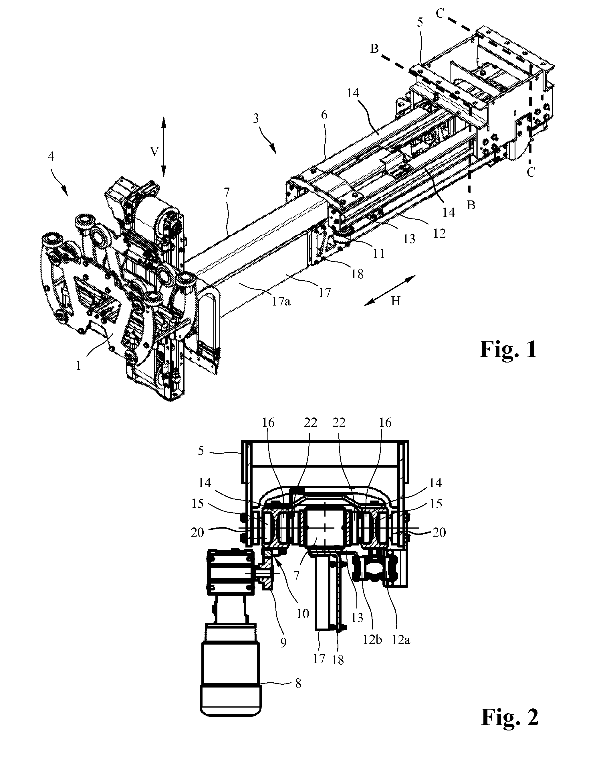
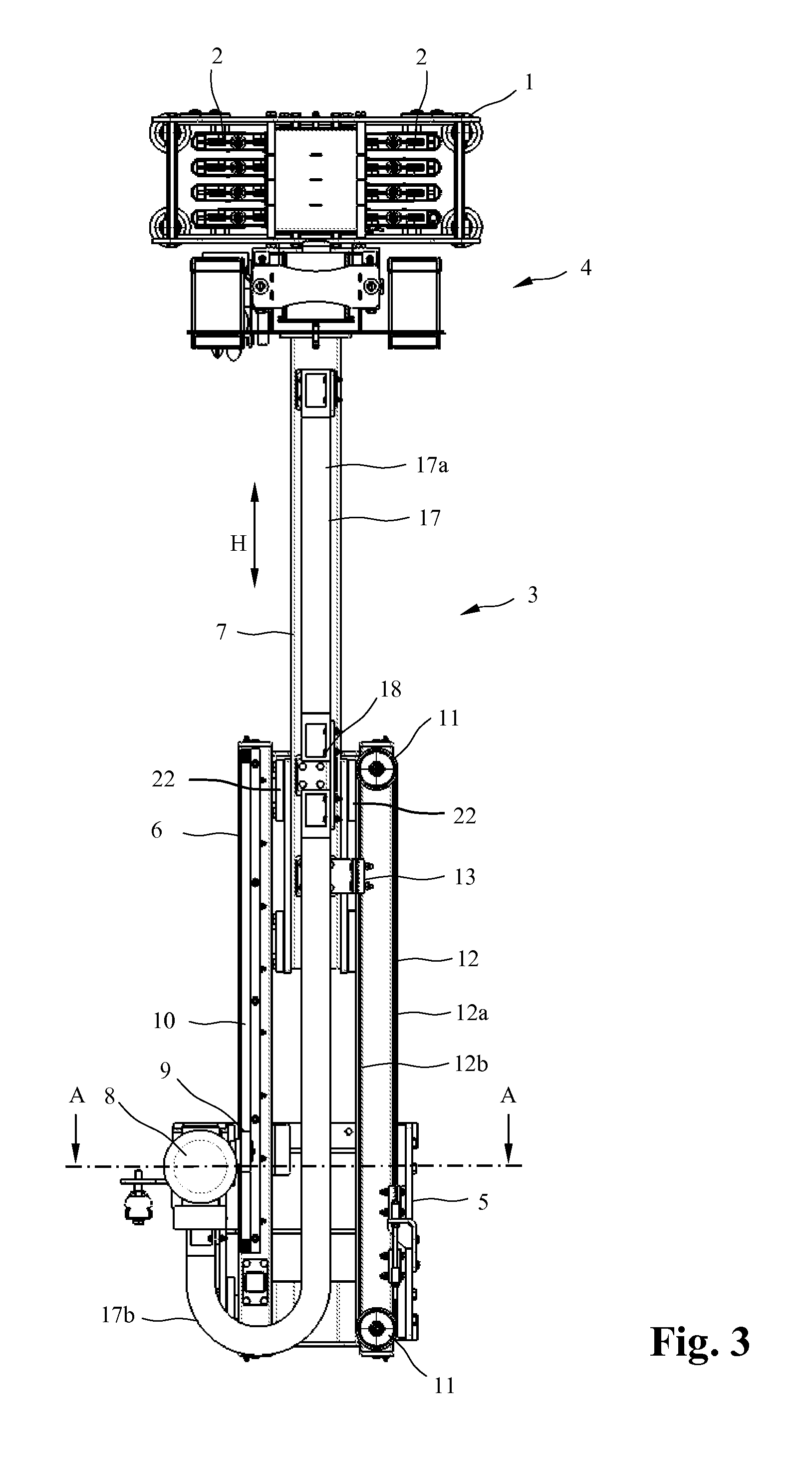
An advancing unit for positioning a current collector unit having at least one extension, which is guided in a fastening unit so that the extension can be moved linearly and which has a cavity, open on a longitudinal side extending in the advancing direction and the inner surface of which forms a contact surface for guiding elements arranged on the fastening unit. A flexible band is arranged on the extension. One section of the flexible band at least partially covers the open longitudinal side of the cavity along a section protruding from the fastening device, and another section of the flexible band is located in a reservoir. A first end of the band is connected to the fastening unit or to an end of the extension and the second end is supported on a tensioning device under a tensile stress in the longitudinal direction, which tensioning device, in the event of a motion of the extension by means of which the protruding section is shortened or lengthened, pulls the band into the reservoir or outputs the band from the reservoir by the same length and at the same velocity.

Description

FIELD OF THE INVENTION[0001]The invention concerns an advancing unit for the positioning of a current collector unit according to the preamble of claim 1.BACKGROUND OF THE INVENTION[0002]Such an advancing unit is known from DE 10 2011 001 712 A1. It is a component of a current collector system, which is fastened to a supporting leg of a crane and can be moved with it along a line on which at least one current track is located. A current collector unit of the current collector system can produce an electric contact with the current track, wherein, for the purpose, the current collector unit can be moved to an introduction device of the path, via the advancing unit which can be displaced in the horizontal direction. The current collector unit can be moved in a vertical direction, supported in a guide on the horizontal advancing unit, wherein current collector contacts of the current collector unit can be moved to the current track in a vertical direction by means of the introduction d...

Claims


Application Information

Patent Timeline
IPC IPC(8): B60L5/39B60L5/08
CPCB60L5/08B60L5/39B60L5/38B60L2200/26B66C13/12B66C19/007
Inventor MULLER, JORG
Owner CONDUCTIX WAMPFLER
Learn More