
An automobile instrument test case suite generating method

A test case set, automotive instrumentation technology, applied in software testing/debugging, instrumentation, error detection/correction, etc., can solve the problems of high test efficiency and cost, and the semi-automatic generation of test cases is not very satisfactory. The effect of flexibility and scalability

Inactive Publication Date: 2016-08-17
AEROSPACE HI TECH HLDG GROUP
View PDF3 Cites 0 Cited by
  • Summary
  • Abstract
  • Description
  • Claims
  • Application Information

AI Technical Summary

Problems solved by technology

[0003] The purpose of the present invention is to solve the problems that the existing test cases have extremely high requirements for knowledge and experience, the test efficiency and cost are very high, they are easily affected by the subjective influence of testers, and the effect of semi-automatically generated test cases is not very ideal. A method for generating test case sets for automotive instrumentation is proposed

Method used

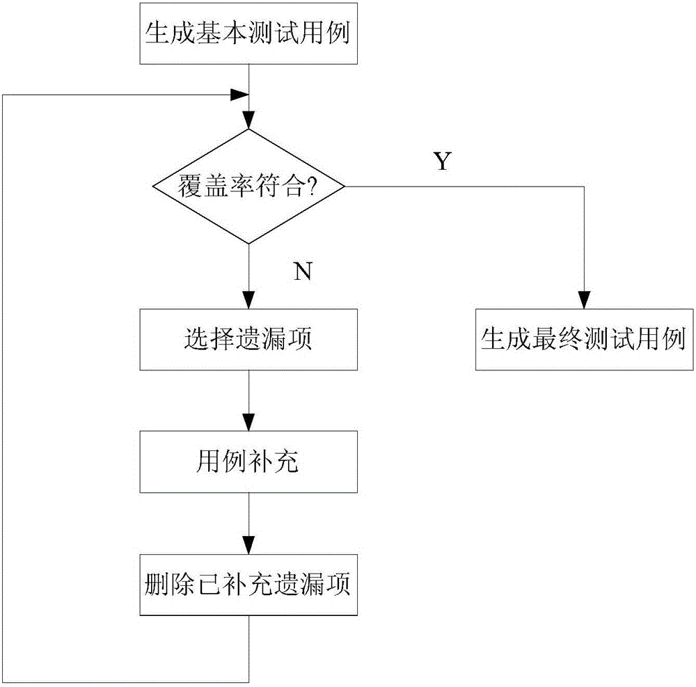

Image

  • An automobile instrument test case suite generating method
  • An automobile instrument test case suite generating method

Examples


specific Embodiment approach 1

[0021] Embodiment 1: A method for generating a test case set for an automobile instrument in this embodiment is specifically prepared according to the following steps:

[0022] Step 1. Use the combined coverage algorithm to generate the test case set of the vehicle meter according to the actual functional characteristics of the vehicle meter; the process principle structure of the combined coverage algorithm is as follows figure 2 shown;

[0023] Step 2. Suppose there are k input parameters in the test case set of automobile instrumentation, and the value of each parameter in the k parameters is t i , i=1, 2, ... n, the total number of values ​​n for each parameter generates n factors in the test case set, and the number of rows r in the test case table is determined according to the n factors in the test case set; among them, t 1 ≥t 2 ≥…t n ;

[0024] Step 3. Coverage is a means of measuring the integrity of the test. It evaluates the completeness of the test cases after...

specific Embodiment approach 2

[0037] Embodiment 2: The difference between this embodiment and Embodiment 1 is that in step 1, a combined coverage algorithm is used to generate a test case set for an automobile instrument according to the actual functional characteristics of the automobile instrument. Specifically:

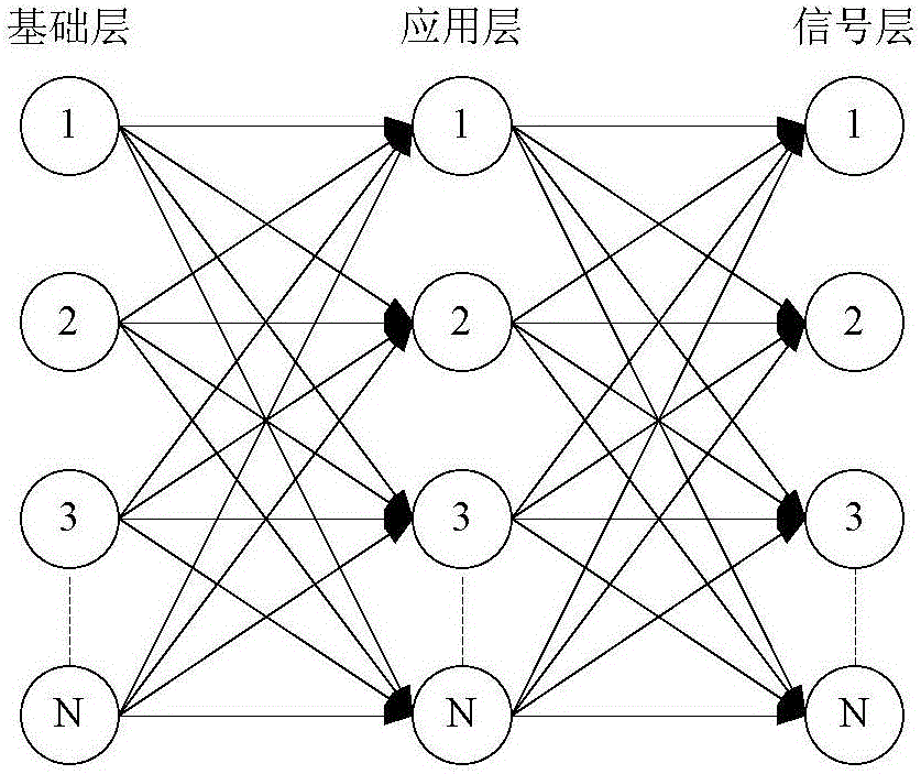
[0038] Step 11. Divide the actual functional characteristics of the car instrument into three layers, the first layer is the basic layer, the second layer is the application layer and the third layer is the signal layer;

[0039] step one or two, figure 2 In terms of network model, the three layers in the network model are the base layer, the application layer and the signal layer. The base layer, the application layer and the signal layer respectively contain N nodes; one node is selected from the base layer, the application layer and the signal layer respectively. , the selected three nodes will be a path;

[0040] Steps 1 and 3: Repeat steps 1 and 2 to select all nodes in the base layer, the...

specific Embodiment approach 3

[0042] Embodiment 3: The difference between this embodiment and Embodiment 1 or 2 is that the basic layer is used to control basic function information: the basic layer includes a display device, an indicator light, a liquid crystal display, a sound alarm device, function keys, output Instrumentation and power management devices. Other steps and parameters are the same as in the first or second embodiment.


PUM


Abstract

The invention provides an automobile instrument test case suite generating method and aims to solve the problems that conventional test cases propose higher requirements for knowledge and experience, the test efficiency is low, the cost is high, the test cases are liable to be subjectively influenced by testing staff, and the effect of semi-automatically generating test cases is not ideal. The method comprises the steps of firstly, generating an automobile instrument test case suite; secondly, determining the number of rows r of a test case table; thirdly, determining the coverage rate p of m parameters; fourthly, generating a final test case suite when r is not less than max (ti1*ti2*...tik) and p is not less than (t1*t2*...tn) / (t1*t2*...tm); fifthly, if the conditions in the fourth step are not met, repeating the previous four steps until the conditions are met. The method is applicable to the field of automobile instrument test case suite generating methods.

Description

technical field [0001] The invention relates to a method for automatically generating a test case set of an automobile instrument. Background technique [0002] The car instrument is an important part of the car, it is the basis for the driver and the car status indication, so the research and development quality of the instrument is very important. It ensures product quality during the research and development stage. Test cases are the basis for instrument testing, and the quality of test case design will directly affect the success of the test work. At present, most companies are still in the stage of manually writing test cases, which has extremely high requirements on the knowledge and experience of testers. In addition, the efficiency and cost of testing in this way are very high, and they are easily affected by the subjective influence of testers. Some companies also use the semi-automatic method of generating test cases, but the effect is not very satisfactory, and ...

Claims


Application Information

Patent Timeline
IPC IPC(8): G06F11/36
CPCG06F11/3684
Inventor 侯影李宏梅芦婷郑伟
Owner AEROSPACE HI TECH HLDG GROUP
Learn More