Integrated system for cleaning bone and milling the cleaned bone to form bone chips

a technology of integrated system and cleaning bone, which is applied in the field of integrated system for cleaning bone and milling the cleaned bone to form bone chips, can solve the problems of contamination of the bone, skin of the surgical personnel may come into direct contact with the bone, and the gloves worn by the surgical personnel are tearing and other problems

Active Publication Date: 2014-03-18
STRYKER CORP
View PDF8 Cites 7 Cited by
  • Summary
  • Abstract
  • Description
  • Claims
  • Application Information

AI Technical Summary

Benefits of technology

[0013]The integrated system of this invention includes components for both cleaning and milling the bone stock. By having the mechanized cleaning head perform the cleaning process, the need for operating room personnel to perform this task is eliminated. In many situations, the cleaning head cleans bone stock in less time than it takes an individual to perform the same task.
[0014]Still another advantage of the integrated system of this invention is that a single unit, the base unit, provides the motive power needed to actuate the cleaning element internal to the cleaning head and the mill element internal to the mill head. The need to provide essentially duplicative power units, one for each head, is eliminated.
[0018]A further advantage of the above alternative versions of the invention is that once the bone stock is placed in the cleaning head, the need for surgical personnel to handle bone is substantially eliminated.

Problems solved by technology

Nevertheless, prior to this process, it is still necessary to clean the bone to remove ligaments and other tissue that are not suitable stock for forming bone chips.
Moreover, to perform the cleaning process, the surgical personnel may need to firmly grasp the bone.
Exerting such force on the bone may cause tearing of the gloves worn by the surgical personnel.
Such tearing could result in the possibility that skin of the surgical personnel may come into direct contact with the bone.
This contact can result in contamination of the bone.

Method used


Image

  • Integrated system for cleaning bone and milling the cleaned bone to form bone chips
  • Integrated system for cleaning bone and milling the cleaned bone to form bone chips
  • Integrated system for cleaning bone and milling the cleaned bone to form bone chips

Examples


Embodiment Construction

I. Overview

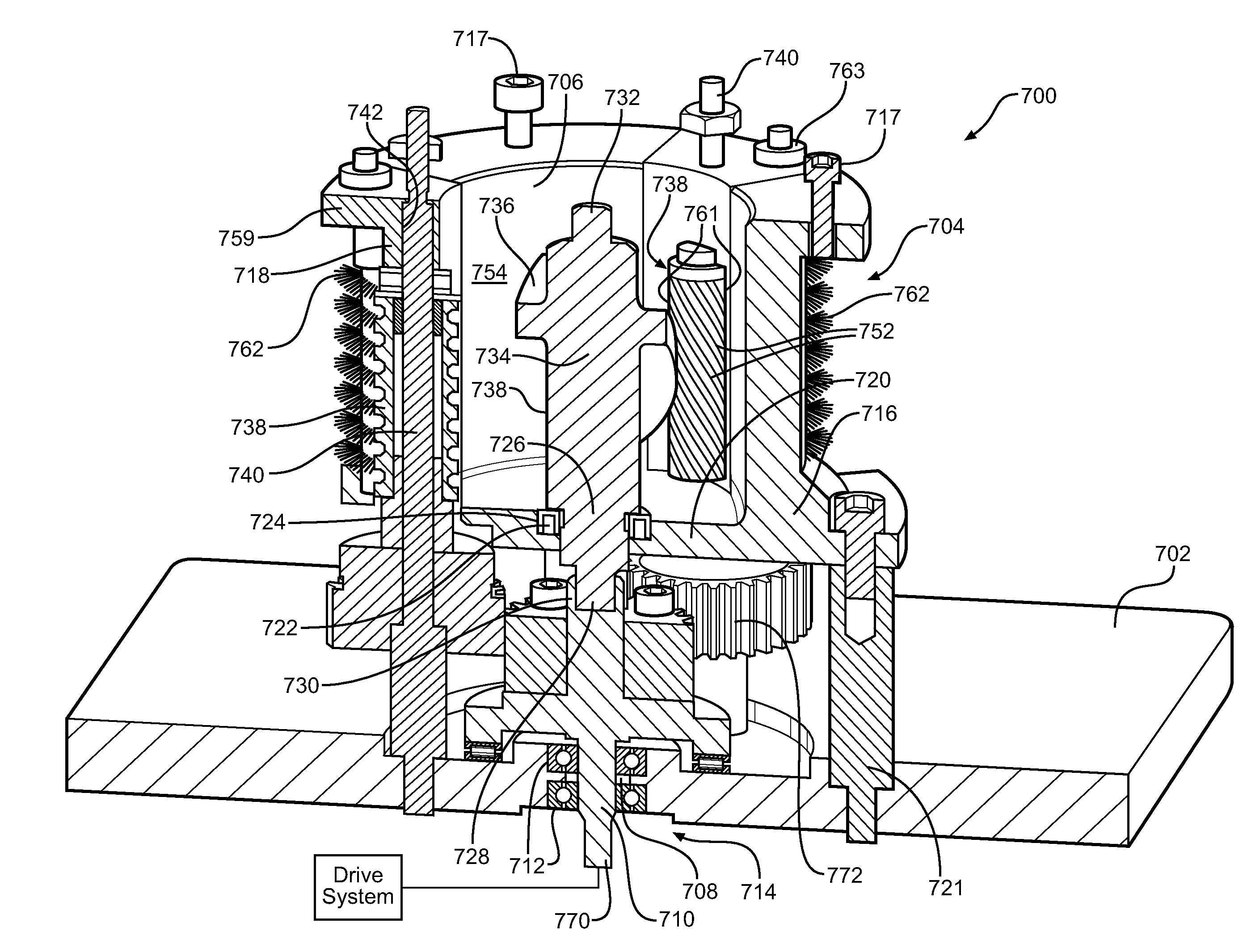
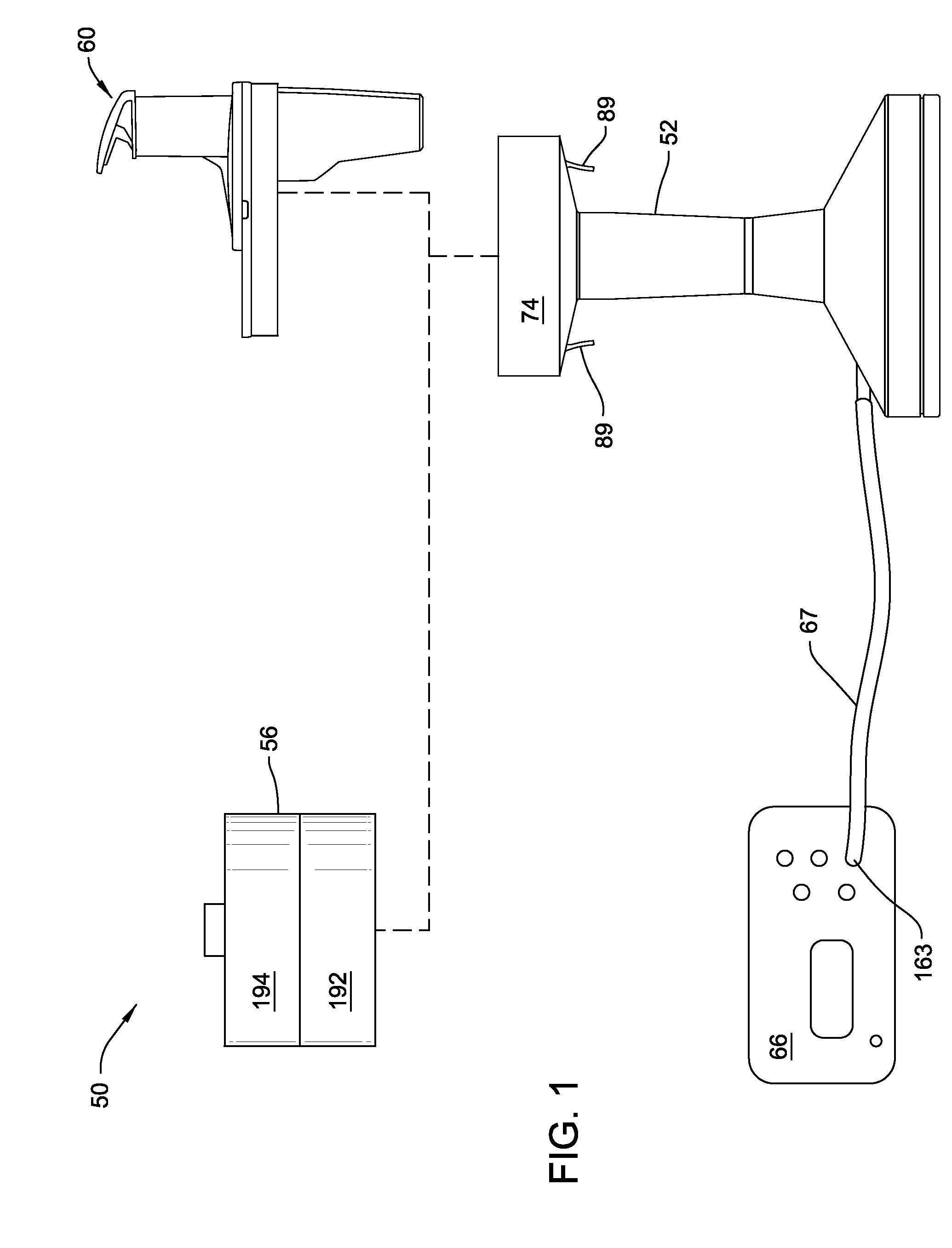
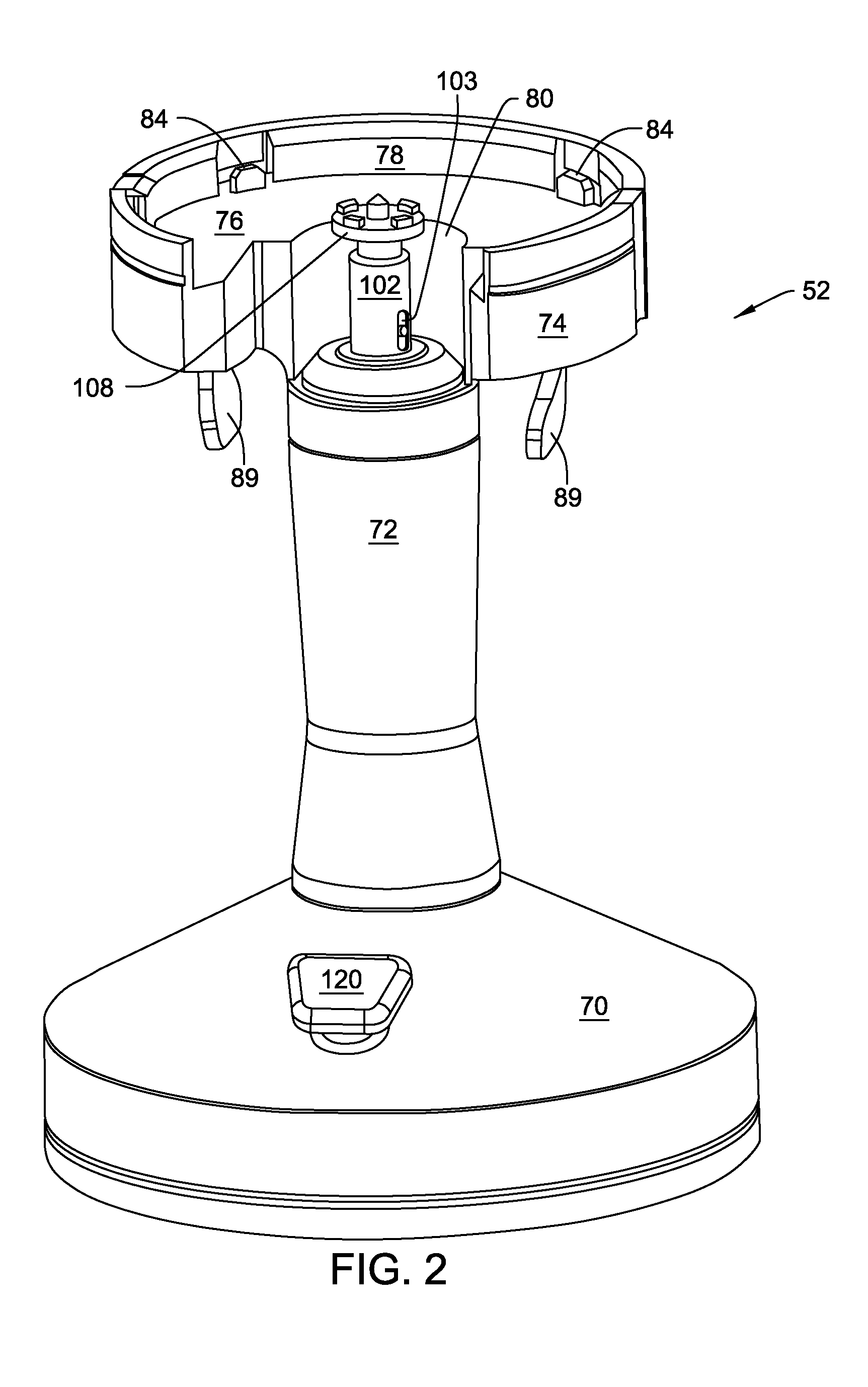
[0077]FIG. 1 illustrates the basic components of integrated system 50 of this invention for cleaning and milling bone stock. System 50 includes a base unit 52. Internal to the base unit 52 is a motor 54, (FIG. 3). A cleaning head 56 is removably attached to the base unit 52. Internal to the cleaning head are brushes 58 and 59 (FIG. 7). Cleaning head 56 is configured so that, when the cleaning head 56 is attached to the base unit 52, brush 58 is connected to the motor 54 so as to be actuated by the motor 54. The system 50 includes a mill head 60 that, like cleaning head 56, is configured to be removably attached to the base unit 52. A mill element 62 (FIG. 16), sometimes referred to as a cutting device, is moveably mounted inside, the mill head 60. Mill element 62 includes features that, when the mill head 60 is mounted to the base unit 52 couple the mill element to the motor 54.

[0078]Also part of system 50 is a control console 66. Control console 66 supplies the energizat...


PUM


Abstract

A system for cleaning bone that includes a base unit with a motor, a cleaning head (56) with a brush (58) and mill head with a mill element. Both the cleaning head and the mill head are designed to be coupled to the base unit. Both the brush and mill element have features that facilitate their coupling to the motor. When the cleaning head is attached to the base unit, a motor in the base unit rotates the brush to clean the bone. When the mill head is attached to the vase unit, the base unit motor actuates the mill element to convert the cleaned bone into bone chips.

Description

RELATIONSHIP TO EARLIER FILED APPLICATIONS[0001]This application is a continuation of PCT Application No. PCT / US / 2010 / 055646 filed 5 Nov. 2010. PCT Application No. PCT / US / 2010 / 055646 is a non-provisional of U.S. Provisional App. No. 61 / 258,667 filed 6 Nov. 2009. The contents of the above-listed priority applications are explicitly incorporated herein by reference.FIELD OF THE INVENTION[0002]This invention is directed to a system that first cleans bone stock and, once the bone stock is cleaned, mills the bone to form bone chips.BACKGROUND OF THE INVENTION[0003]There are a number of different surgical procedures in which chip-sized bone is used as filler adjacent other sections of bone. For example, in a spinal fusion procedure, it is a known practice to place a compound formed out of milled bone around the rods used to hold adjacent vertebra in alignment. This compound serves as a lattice upon which the tissues forming the vertebra grow so as to form a foundation of bone around the r...

Claims


Application Information

Patent Timeline
Patent Type & Authority Patents(United States)
IPC IPC(8): A61B17/00
CPCA61F2/4644A61F2002/4645A61F2002/4646
Inventor CHAMBERLIN, CHRISDIEHL, ERIC K.BERNERO, JOHNLAM, VINCENTORAND, AUSTIN
Owner STRYKER CORP
Why Eureka
Try Eureka