Motor and motor for electric power steering

a technology for electric steering and motors, applied in the direction of dynamo-electric components, transportation and packaging, association with control/drive circuits, etc., can solve the problems of complicated connection of lead wires and control units, and achieve the effect of small axial dimension and convenient cable connection

Active Publication Date: 2014-09-23
DENSO CORP
View PDF20 Cites 0 Cited by
  • Summary
  • Abstract
  • Description
  • Claims
  • Application Information

AI Technical Summary

Benefits of technology

[0004]Accordingly, it is an objective of the present invention to provide a motor and a motor for an electric power steering that have a small axial dimension and facilitate cable connection.

Problems solved by technology

Additionally, it is complicated to connect each one of the lead wires, which are extended out from the motor body, to the control unit.

Method used


Image

  • Motor and motor for electric power steering
  • Motor and motor for electric power steering
  • Motor and motor for electric power steering

Examples


Embodiment Construction

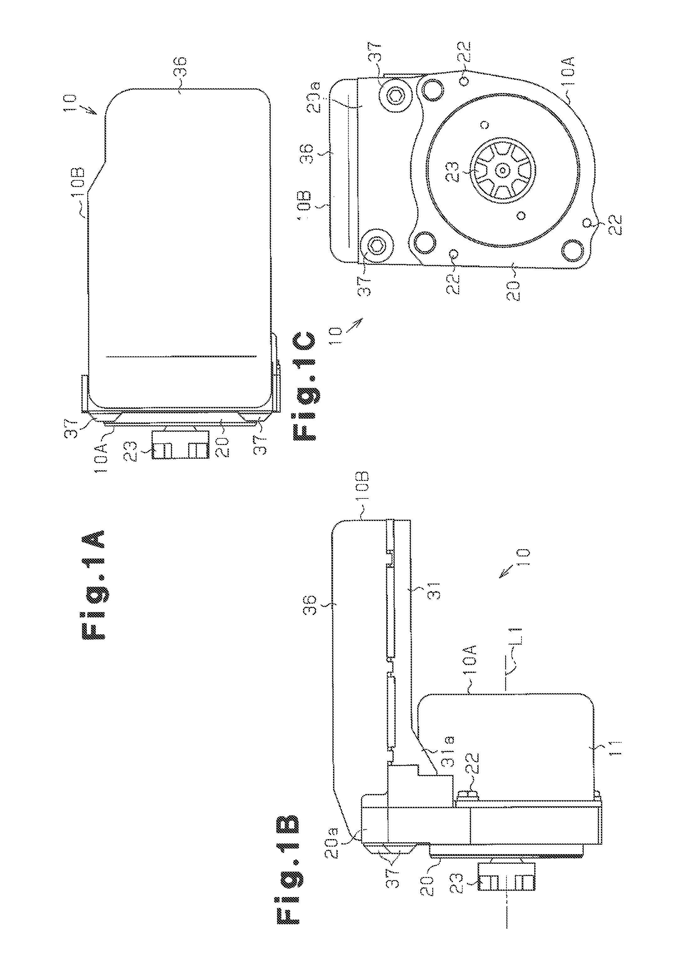
[0020]One embodiment of a motor according to the present invention employed in an electric power steering (EPS) will now be described with reference to FIGS. 1A to 7.

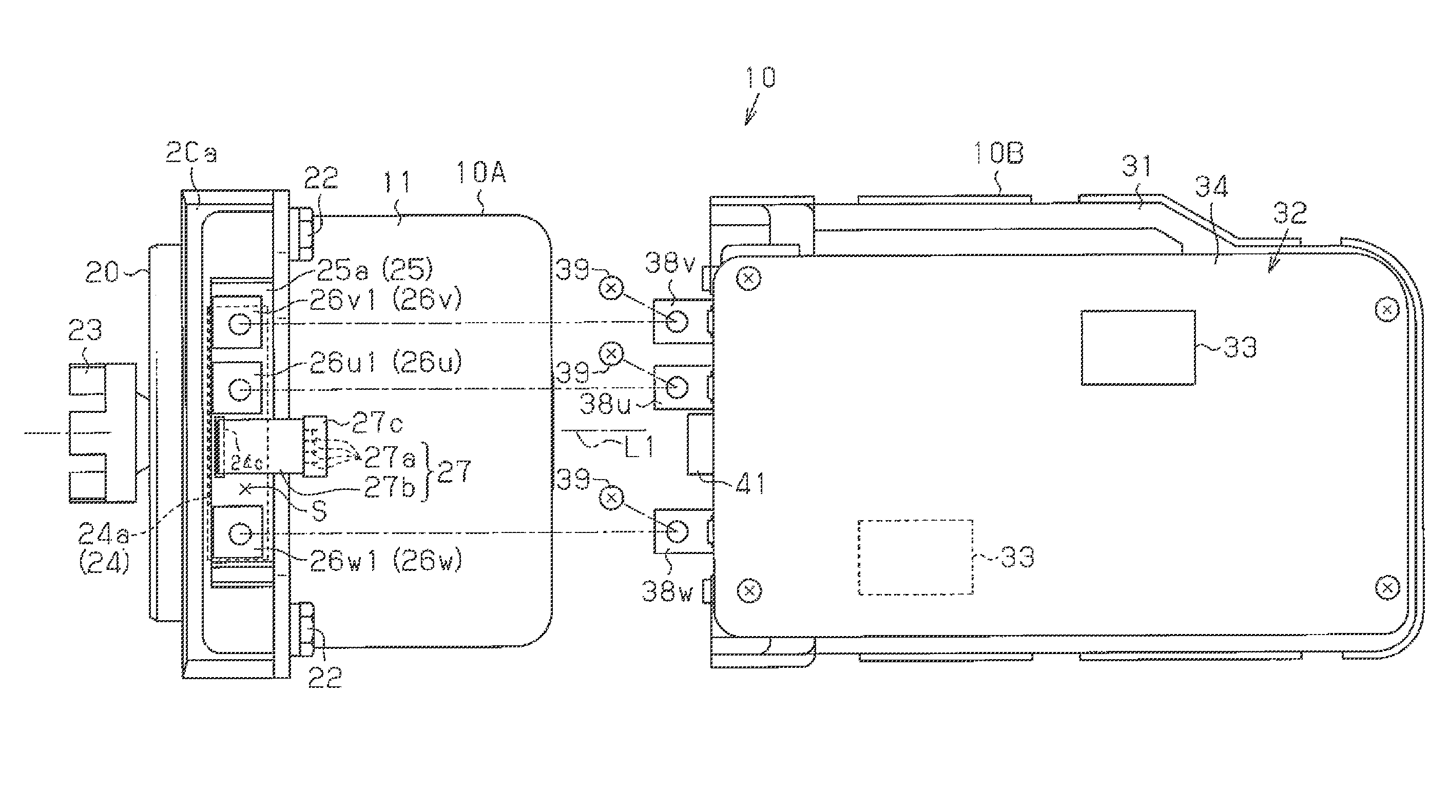
[0021]As illustrated in FIGS. 1A to 1C and 2, a motor 10 has a motor body 10A and a control unit 10B, which is joined to the motor body 10A.

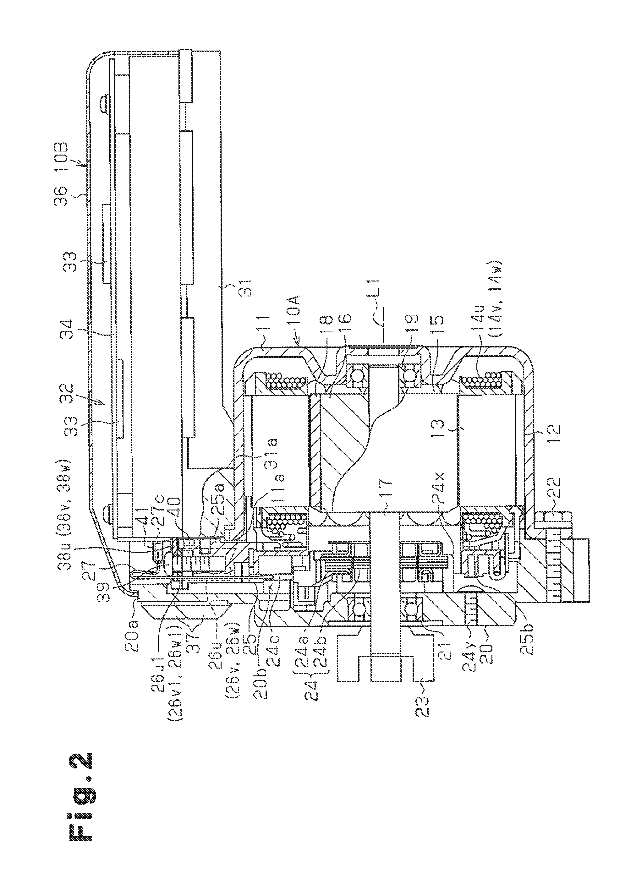
[0022]The motor body 10A is formed by a brushless motor. The motor body 10A has a motor case 11 having a lidded cylindrical shape. An annular stator 12 is fixed to the inner peripheral surface of the motor case 11. A rotor 15 is arranged in the stator 12. Drive coils 14u, 14v, 14w for three phases, which are U, V, and W phases, are mounted in a stator core 13 of the stator 12. When three phase electric current is supplied from a control unit 10B to the stator 12, the stator 12 produces a rotating magnetic field, thus rotating the rotor 15.

[0023]The rotor 15 has a rotor core 16, a rotary shaft 17, which is received in a central portion of the rotor core 16, and a magnet 18 fixed to t...


PUM


Abstract

A motor has a motor body and a control unit, which is joined to the motor body. A resolver is connected to the control unit through a flat cable. The flat cable is arranged such that the width direction of the flat cable corresponds with a circumferential direction of the motor body. The flat cable extends outwardly in a radial direction of the motor case.

Description

BACKGROUND OF THE INVENTION[0001]The present invention relates a motor integrated with a control unit and a motor for an electric power steering.[0002]Japanese Laid-Open Patent Publication No. 2003-204654 discloses an electric power steering having a motor. The electric power steering has a control unit attached to a side surface of a motor body. A drive control circuit in the control unit is electrically connected to the motor body. The motor body is a brushless motor having a resolver for detecting the rotational position of a rotor. The drive control circuit generates three phase drive current corresponding to the rotational position of the rotor based on a signal provided by the resolver. The drive current is supplied to drive coils of the corresponding phase, thus controlling rotation of the motor body.[0003]In this motor, the resolver in the motor body and the drive control circuit in the control unit are connected to each other through a plurality of flexible lead wires. The ...

Claims


Application Information

Patent Timeline
Patent Type & Authority Patents(United States)
IPC IPC(8): H02K11/00
CPCH02K11/0073B62D5/0406H02K29/06H02K11/33
Inventor YAMASHITA, YUUJISUZUKI, NORIYUKITODA, YASUYOSHIKAWATA, HIROYUKI
Owner DENSO CORP
Why Eureka
Try Eureka