Radiation detector and radiographic imaging apparatus
a radiographic imaging and detector technology, applied in the direction of television systems, instruments, printed circuit non-printed electric components association, etc., can solve the problem of difficult reworking of the connection of the cables to the sensor board, and achieve the effect of facilitating the reworking of the connection of the cable to the substra
- Summary
- Abstract
- Description
- Claims
- Application Information
AI Technical Summary
Benefits of technology
Problems solved by technology
Method used
Image
Examples
first embodiment
[0037]A radiographic imaging apparatus of the present embodiment has a function of capturing a radiographic image of an object to be imaged, by detecting radiation transmitted through a subject, which is an object to be imaged, and outputting image information representing a radiographic image of the subject.
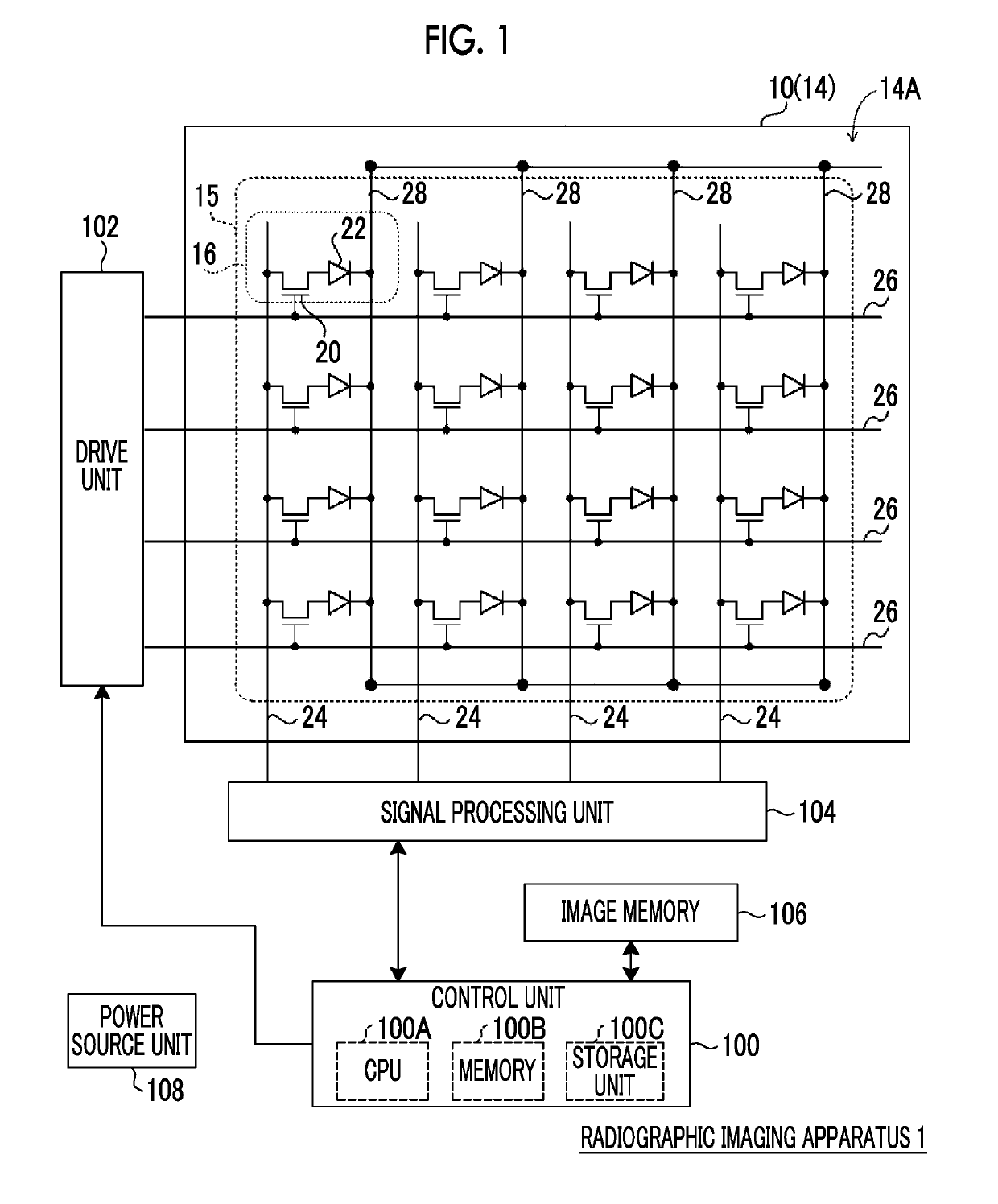
[0038]First, the outline of an example of the configuration of an electrical system in the radiographic imaging apparatus of the present embodiment will be described with reference to FIG. 1. FIG. 1 is a block diagram illustrating an example of the configuration of main parts of the electrical system in the radiographic imaging apparatus of the present embodiment.
[0039]As illustrated in FIG. 1, the radiographic imaging apparatus 1 of the present embodiment includes a radiation detector 10, a control unit 100, a drive unit 102, a signal processing unit 104, an image memory 106, and a power source unit 108.
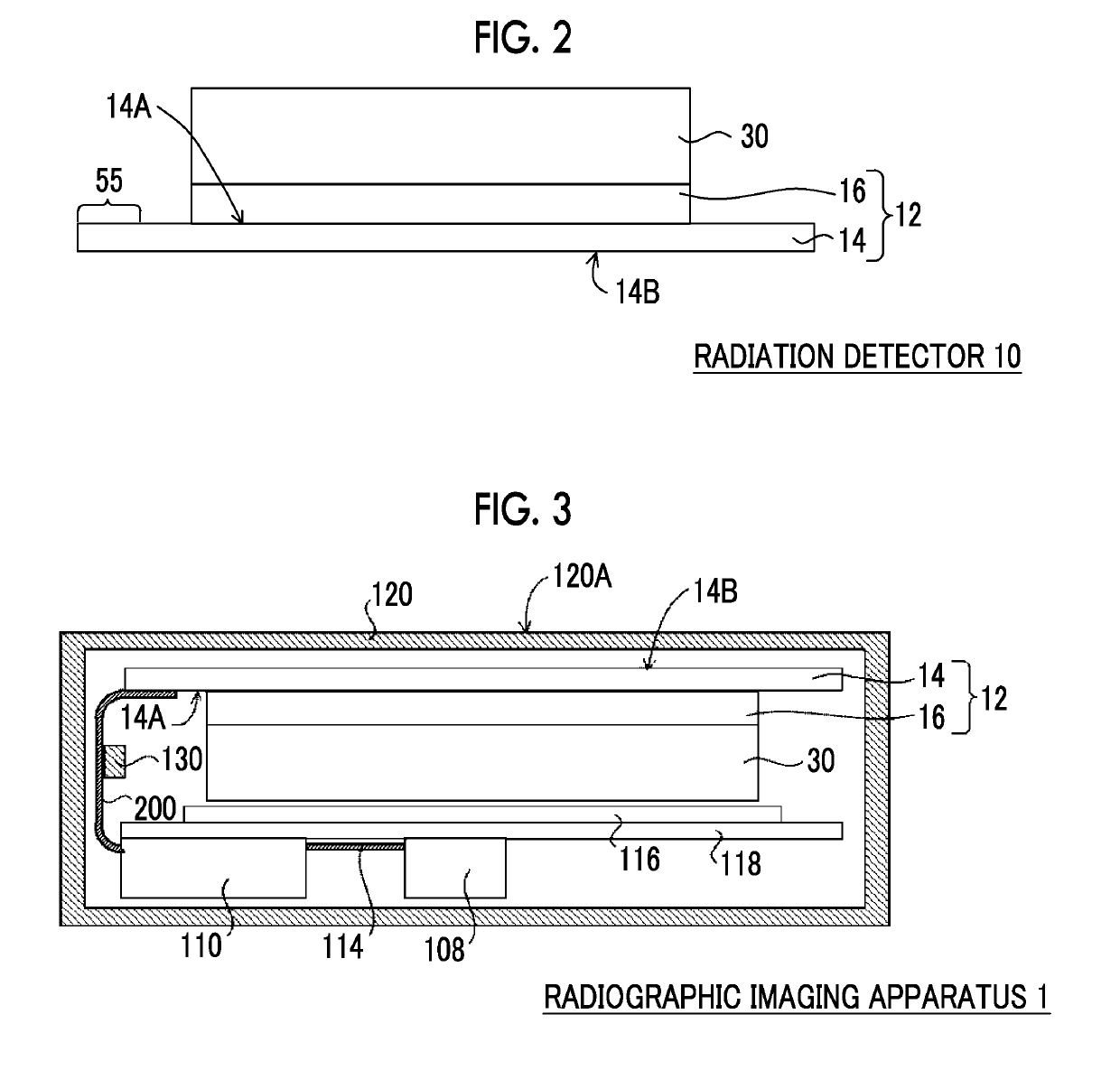
[0040]The radiation detector 10 includes a sensor board 12 (refer to FIG. 2...
second embodiment
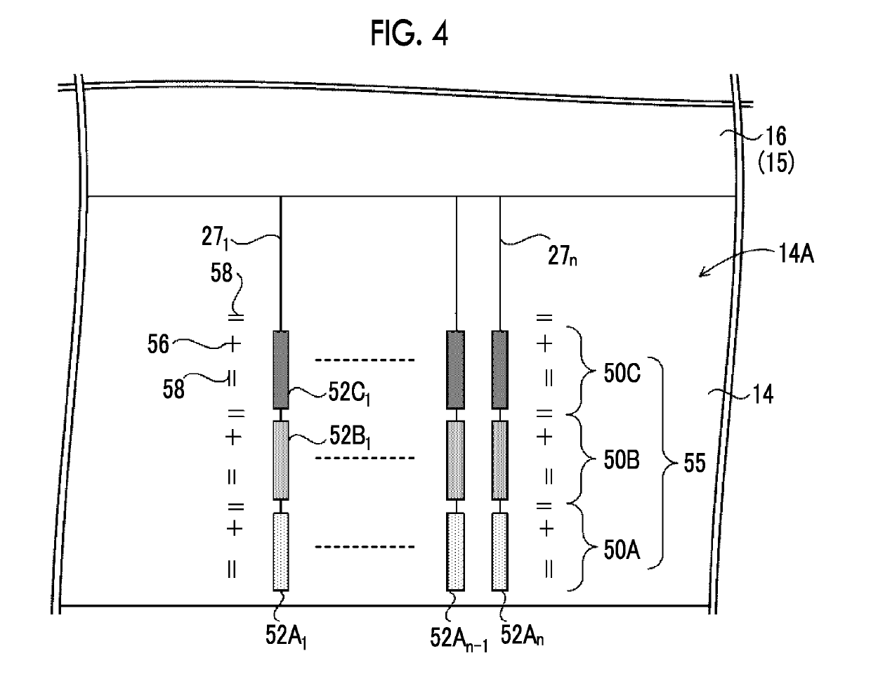
[0098]Since a radiation detector 10 of the present embodiment is different from the first embodiment in terms of the terminal region part 55, the terminal region part 55 of the present embodiment will be described. A plan view illustrating the outline of an example of the terminal region part 55 provided at the outer periphery of the substrate 14 of the sensor board 12 in the radiation detector 10 of the present embodiment is illustrated in FIG. 8.
[0099]As illustrated in FIG. 8, the terminal region part 55 of the radiation detector 10 of the present embodiment includes the first terminal region 50A and the second terminal region 50B that are aligned along the outer edge of the substrate 14.
[0100]As illustrated in FIG. 8, in a case where the first terminal region 50A and the second terminal region 50B are aligned along the outer edge of the substrate 14, even in a case where the reworking is performed unlike the radiation detector 10 of the above first embodiment, the distance from t...
PUM
 Abstract
Description
Claims
Application Information
 - R&D
- Intellectual Property
- Life Sciences
- Materials
- Tech Scout
- Unparalleled Data Quality
- Higher Quality Content
- 60% Fewer Hallucinations
Browse by: Latest US Patents, China's latest patents, Technical Efficacy Thesaurus, Application Domain, Technology Topic, Popular Technical Reports.
© 2025 PatSnap. All rights reserved.Legal|Privacy policy|Modern Slavery Act Transparency Statement|Sitemap|About US| Contact US: help@patsnap.com


