Directional differential pressure detector

a detector and differential pressure technology, applied in the direction of pressure difference measurement between multiple valves, instruments, golf clubs, etc., can solve problems such as irritating sound

Active Publication Date: 2014-12-16
AIRFLOW DIRECTION INC
View PDF20 Cites 16 Cited by
  • Summary
  • Abstract
  • Description
  • Claims
  • Application Information

AI Technical Summary

Benefits of technology

[0008]The inventor has appreciated that it would be beneficial to provide a simple detection system for fluid (e.g., air) flow that provides quantitative information regarding different degrees of differential pressure that may exist between adjacent spaces (e.g., enclosed rooms, compartments, corridors, etc.) and the associated causal direction of fluid flow between the spaces. As an example, the differential fluid (e.g., air) pressure between, e.g., two adjacent enclosed spaces A and B separated by a wall may be zero or more positive in space A than space B or more positive in space B than space A, causing a potential of air to flow between the spaces from zero or in the direction from space A to B or in the direction from space B to space A, respectively. The relative pressure between space A and B forms a differential pressure and depending on which space is of higher pressure, the relative pressure is directional in nature, i.e., causes a fluid to flow in a direction from a higher pressure region towards a lower pressure region and therefore a directional differential pressure exists.
[0009]Directional differential pressure detectors described herein may provide information that allows an observer to know immediately whether or not the room, as compared with its immediate surroundings, exhibits a particular direction of air flow, into or out of the room in response to a particular degree of negative or positive pressure difference, which may be required under set protocols for the room. Further, directional differential pressure detectors of the present disclosure may provide an observer not only with an indication that the direction of air flow from one space to another is in the desired direction, but also may inform the observer with the approximate magnitude of pressure difference between the spaces.
[0016]The device may further include a sealing material (e.g., gasket) placed in contact with the exterior surface of the conduit so as to provide a seal between the surface of the wall and the conduit when the device is installed. Accordingly, transfer of potentially contaminated air between a space and the interior cavity of a hollow wall may be substantially prevented. As the conduit may be positioned at a particular angle of inclination when installed, the sealing material may be flexible to provide and maintain a seal as well as accommodate appropriate adjustment(s) in position of the conduit (e.g., from one angle of incline to another). Yet, the sealing material may also be firm enough to provide a suitable amount of support for the tilted conduit (e.g., to maintain the position / orientation of the conduit).
[0019]In yet another embodiment, a device for detecting a directional differential pressure between two rooms is provided. The device includes an elongated conduit arranged to extend through a wall separating the two spaces, the conduit having openings at opposite ends that permit fluid flow between the two spaces through the conduit; a movable element disposed within the conduit adapted to be moved from one region of the conduit toward an opposing region in response to the differential pressure; and a sound attenuator adapted to reduce noise upon the movable element reaching one of the two conduit ends.

Problems solved by technology

Such a sound may be irritating to those in close proximity to the lower end of the conduit, particularly if repeated frequently.

Method used


Image

  • Directional differential pressure detector
  • Directional differential pressure detector
  • Directional differential pressure detector

Examples


Embodiment Construction

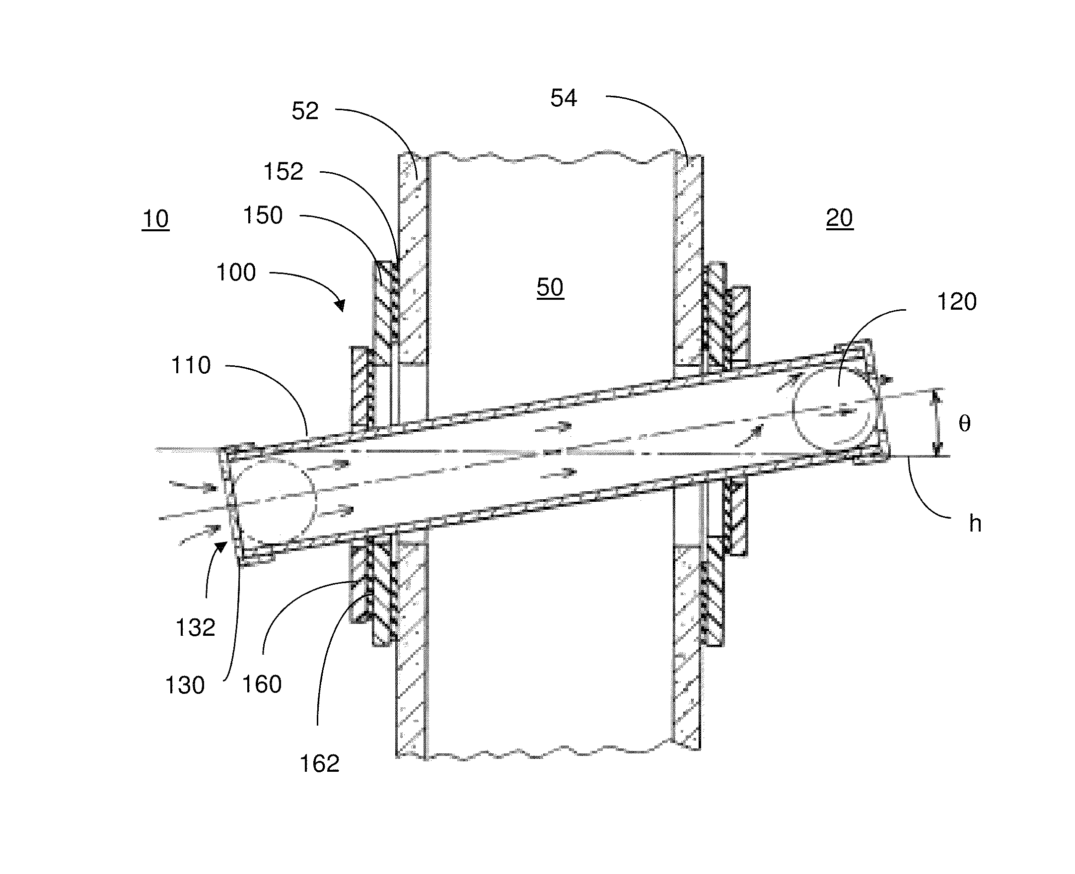
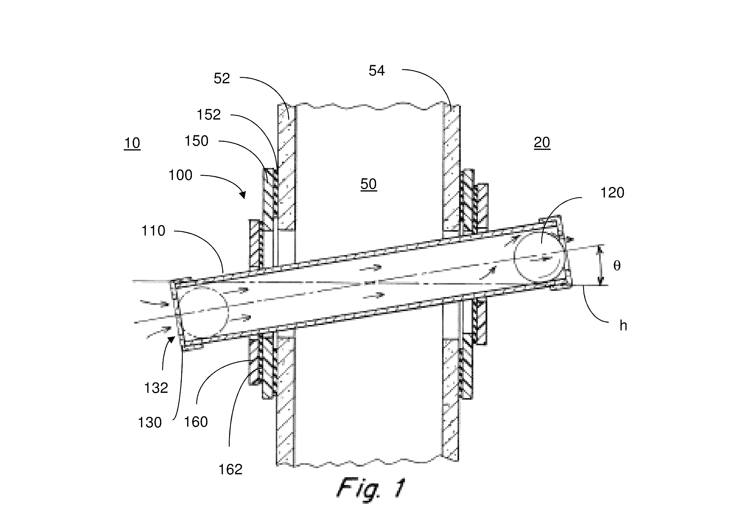
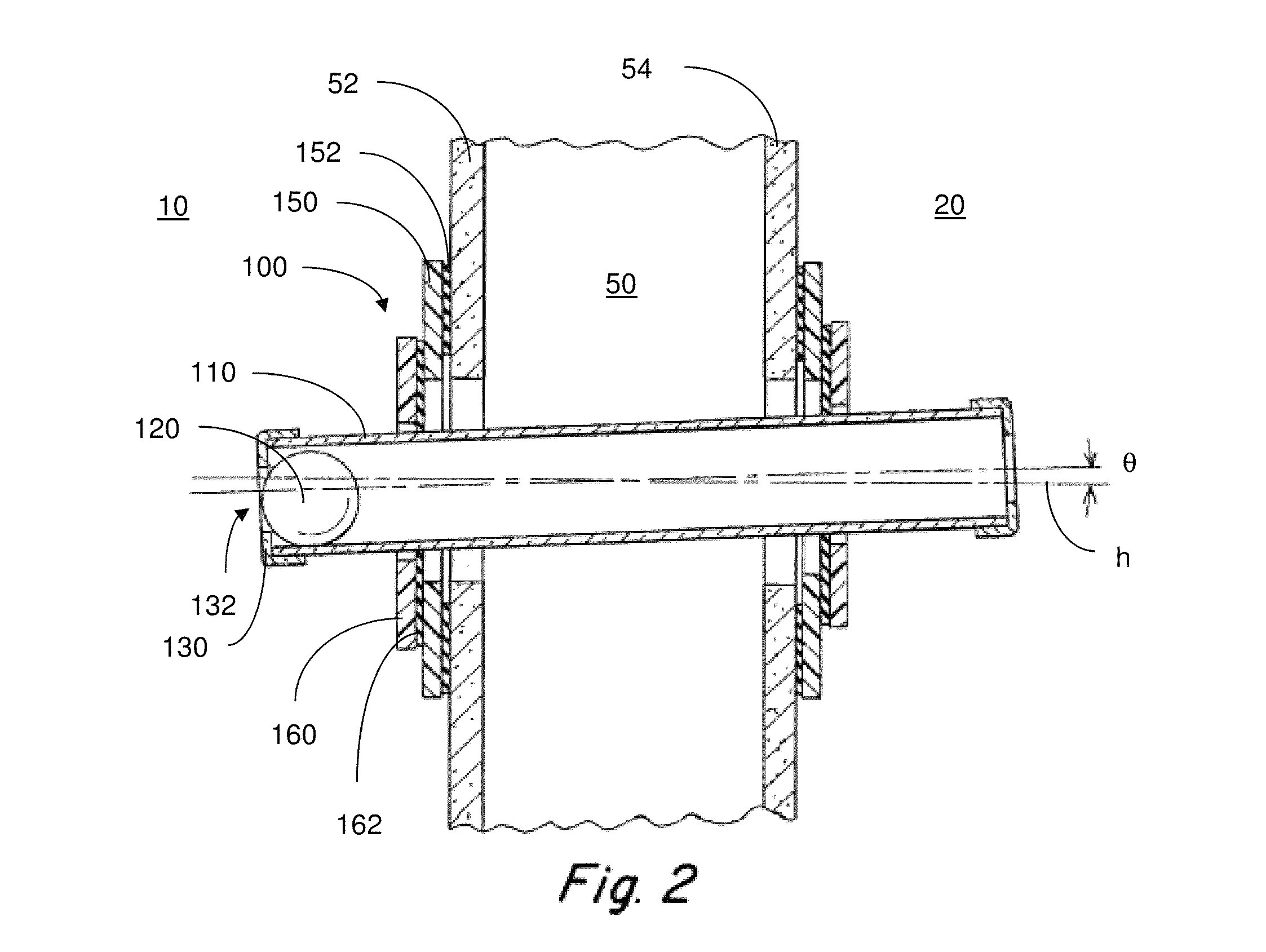
[0051]The present disclosure relates to a device that provides an indication of directional air flow and whether a particular degree of directional differential pressure exists between spaces separated by a wall (e.g., two neighboring rooms). In some embodiments, the device includes an elongated conduit with openings on opposite ends. A ball, or other movable element, is disposed within a lumen of the conduit and may move freely back and forth along the length of the conduit. Restraints or end stops located at opposite ends of the conduit may be used to contain the ball within the conduit so that the ball does not exit from the conduit. The end stops may have openings that allow fluid (e.g., air, inert gas, liquid) to flow through the lumen of the conduit from one end to an opposite end.

[0052]The device may include a differential pressure set point indicator associated with the conduit and a movable element within the lumen of the conduit. The set point indicator may be configured t...


PUM

PropertyMeasurementUnit
differential pressureaaaaaaaaaa
pressureaaaaaaaaaa
angleaaaaaaaaaa

Abstract

Methods and apparatuses for indicating the presence of a directional differential pressure between separated adjacent spaces are provided. A differential pressure set point indicator may be configured to correlate multiple potential angles of inclination of an elongated conduit to respective threshold differential pressures between two spaces which generate net flow of fluid sufficient to cause a lightweight ball to move from one region of the conduit to an opposing region. The elongated conduit may be adjustable in length so as to accommodate installation of the device into walls of varying thickness. The device may include a sound attenuator that reduces noise upon impact of the ball with either end of the conduit. The device may also include a sealing material that is flexible yet firm enough to provide both a seal with the exterior surface of the conduit and support for the conduit when oriented in a tilted configuration.

Description

CROSS-REFERENCE TO RELATED APPLICATIONS[0001]This application claims priority to U.S. Provisional Application No. 61 / 791,703 filed Mar. 15, 2013, entitled “DIRECTIONAL DIFFERENTIAL PRESSURE DETECTOR,” the contents of which are incorporated herein by reference in their entirety.FIELD[0002]Aspects of the present disclosure relate generally to methods and apparatuses for detecting the presence of a directional differential pressure.DISCUSSION OF RELATED ART[0003]Various applications within hospitals, laboratories, pharmaceutical facilities, clean room facilities, etc., often require a particular direction of air flow to be maintained, such as between neighboring rooms, compartments, corridors, ducts, or other spaces. The pressure of a room relative to adjacent space(s) will determine the net direction of air flow through an opening into or out of the room.[0004]For example, a hospital operating room, containing a patient who is undergoing surgery, may be supplied with highly filtered a...

Claims


Application Information

Patent Timeline
Patent Type & Authority Patents(United States)
IPC IPC(8): G01P13/00G01L13/00
CPCG01P13/0066G01L13/00G01P13/0013
Inventor WISEMAN, BRIAN, M.
Owner AIRFLOW DIRECTION INC
Why Eureka
Try Eureka