Tool and set screw for use in spinal implant systems

a technology for spinal implants and screw sets, applied in the field of spinal implant systems, can solve the problems of long administration time, high cost of spinal implants, and tediousness, and achieve the effect of avoiding the very tedious procedure of using different tools

Inactive Publication Date: 2015-03-31
ORTHOPAEDIC INT
View PDF10 Cites 20 Cited by
  • Summary
  • Abstract
  • Description
  • Claims
  • Application Information

AI Technical Summary

Benefits of technology

[0010]It is, therefore, the main object of the present invention to provide a single tool in combination with a set screw to solve the technical problem of avoiding the very the tedious procedure of using different tools in the spinal implant system.

Problems solved by technology

The present spinal implants systems are expensive, tedious and longer to administer since each of the aforementioned general steps require specific and dedicated tools to achieve the desired objectives.

Method used


Image

  • Tool and set screw for use in spinal implant systems
  • Tool and set screw for use in spinal implant systems
  • Tool and set screw for use in spinal implant systems

Examples


Embodiment Construction

[0019]It is to be understood that the phraseologies and terminologies used herein are for the purposes of description and should not be regarded as limiting.

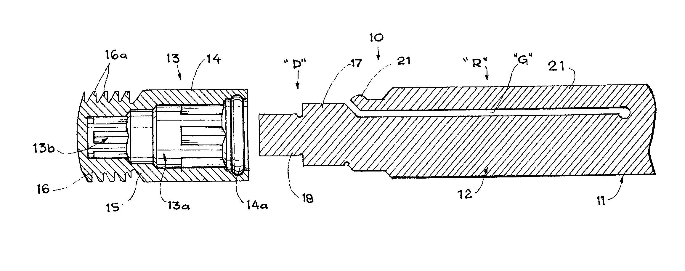
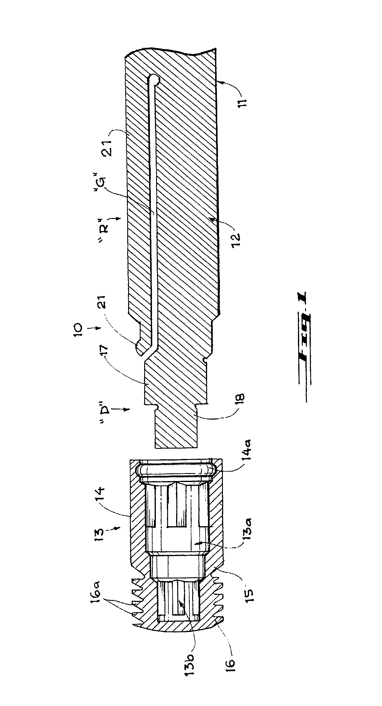
[0020]Referring now to the different views of the drawings, wherein like reference numerals designate the steps, components or elements throughout the ensuing enabling description, the present invention provides for a tool for use in spinal implant systems adapted for the deployment of set screws with a break off head designated as 10.

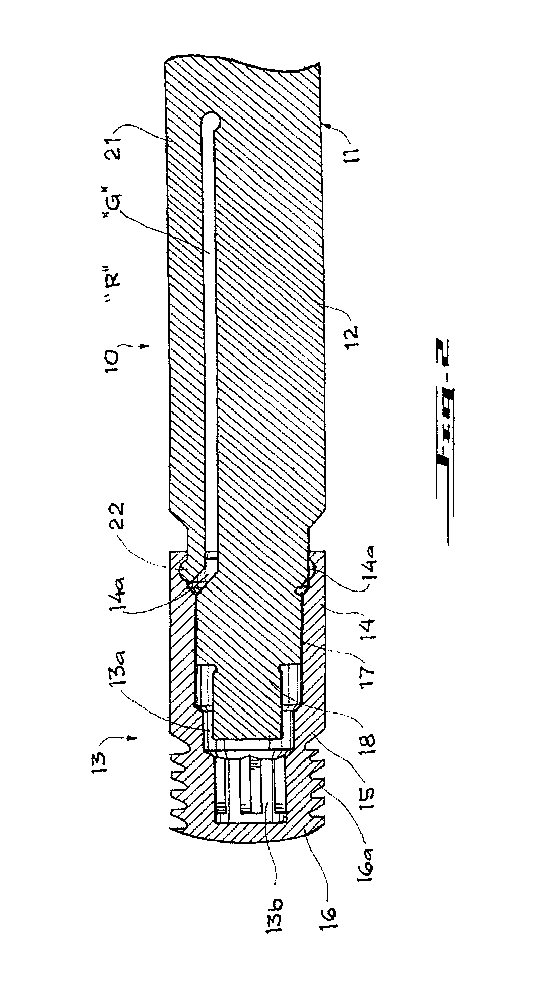
[0021]As shown in FIGS. 1 & 3, the tool 10 comprises a handle portion 11, a stem portion 12 extending from the handle portion 11 and a driving means “D” provided on the tool 10, particularly extending from the stem portion 12 and disposed opposite handle portion 11. A corresponding set screw 13 is provided to engage with the tool 10 to connect the bone screw or hook and spinal rod in the implant system, and comprising a head portion 14, a break-off neck portion 15 and a preferably reduced threaded ...


PUM


Abstract

The present invention relates to a tool in combination with a set screw for use in spinal implant systems, and more particularly to a tool for the deployment of set screws with a break-off neck portion comprising a handle portion, a stem portion extending from the handle portion, a set screw retaining means, and a driving means extending from the stem portion and disposed opposite the handle portion. The driving means is adapted to allow the installation of the set screw to the bone and applying torque for the shearing of the neck portion thereof, and at the same time is adapted to remove the installed screw portion of the said set screw when needed.

Description

[0001]This Application claims the benefit of priority to U.S. Provisional Patent Application Ser. No. 61 / 354,436, entitled “A TOOL AND SET SCREW FOR USE IN SPINAL IMPLANT SYSTEMS”, filed Jun. 14, 2010, the entire disclosure of which is hereby incorporated by reference as if being set forth herein in its entirety.TECHNICAL FIELD[0002]The present invention relates in general to spinal implant systems, but more particularly to a tool adapted for the deployment of set screws with a break-off neck portion featuring a means to allow the installation of the set screw to a spinal bone screw or hook and applying torque for the shearing of the neck portion thereof, and at the same time adapted to remove the installed screw portion of the set screw from the bone screw or hook.BACKGROUND OF THE INVENTION[0003]Existing spinal implant systems employ various instrumentations to secure, adjust and remove the self-limiting set screws to a bone screw or a hook. Tools such as set screw holders, break-...

Claims


Application Information

Patent Timeline
Patent Type & Authority Patents(United States)
IPC IPC(8): A61B17/58A61B17/86A61B17/88A61B19/00
CPCA61B17/8888A61B17/8615A61B2019/307A61B2090/037A61B17/7077A61B17/8886
Inventor SASING, JUDE L.
Owner ORTHOPAEDIC INT
Why Eureka
Try Eureka