Check patentability & draft patents in minutes with Patsnap Eureka AI!

Device and method for checking the integrity of physical objects

a physical object and integrity technology, applied in the field of physical object monitoring devices, can solve the problems of few solutions for reassuring the traveler, lost or forgotten luggage, and inability to meet the needs of travelers, and achieve the effect of low deployment costs

Active Publication Date: 2016-04-26
INRIA NATIONAL INSTITUTE FOR RESEARCH IN COMPUTER SCIENCE AND CONTROL
View PDF48 Cites 0 Cited by
  • Summary
  • Abstract
  • Description
  • Claims
  • Application Information

AI Technical Summary

Benefits of technology

Enables continuous and systematic monitoring of physical objects with low deployment costs, supporting various types of objects and environments without disrupting existing security systems, ensuring the integrity of aggregated objects is maintained.

Problems solved by technology

For example, a very widespread fear of travelers, regardless of their transportation means, is to lose or forget part of their luggage, or further having part of the latter stolen or substituted.
Presently, there are very few solutions for reassuring the traveler, and none of them is satisfactory in practice.
In fact, every time the traveler physically moves away from his luggage including when he / she places them in a compartment provided for this purpose somewhat distant from his / her seating position, he / she is at risk.

Method used


Image

  • Device and method for checking the integrity of physical objects
  • Device and method for checking the integrity of physical objects
  • Device and method for checking the integrity of physical objects

Examples


first embodiment

[0094] the LECT function and the label reader 13 are laid out together so as to sequentially read labels 5. The recording table here assumes the form of a log file grouping the individual E_ID identifiers of the labels 5 read, the data associated with these individual E_ID identifiers, and the reading dates TS of the labels 5.

[0095]In this embodiment, a time delay DT is imposed for the passing of the labels 5 making up a same aggregated object 1. In other words, an aggregated object 1 is entire here if the whole of the labels 5 which make it up is read within the time delay DT.

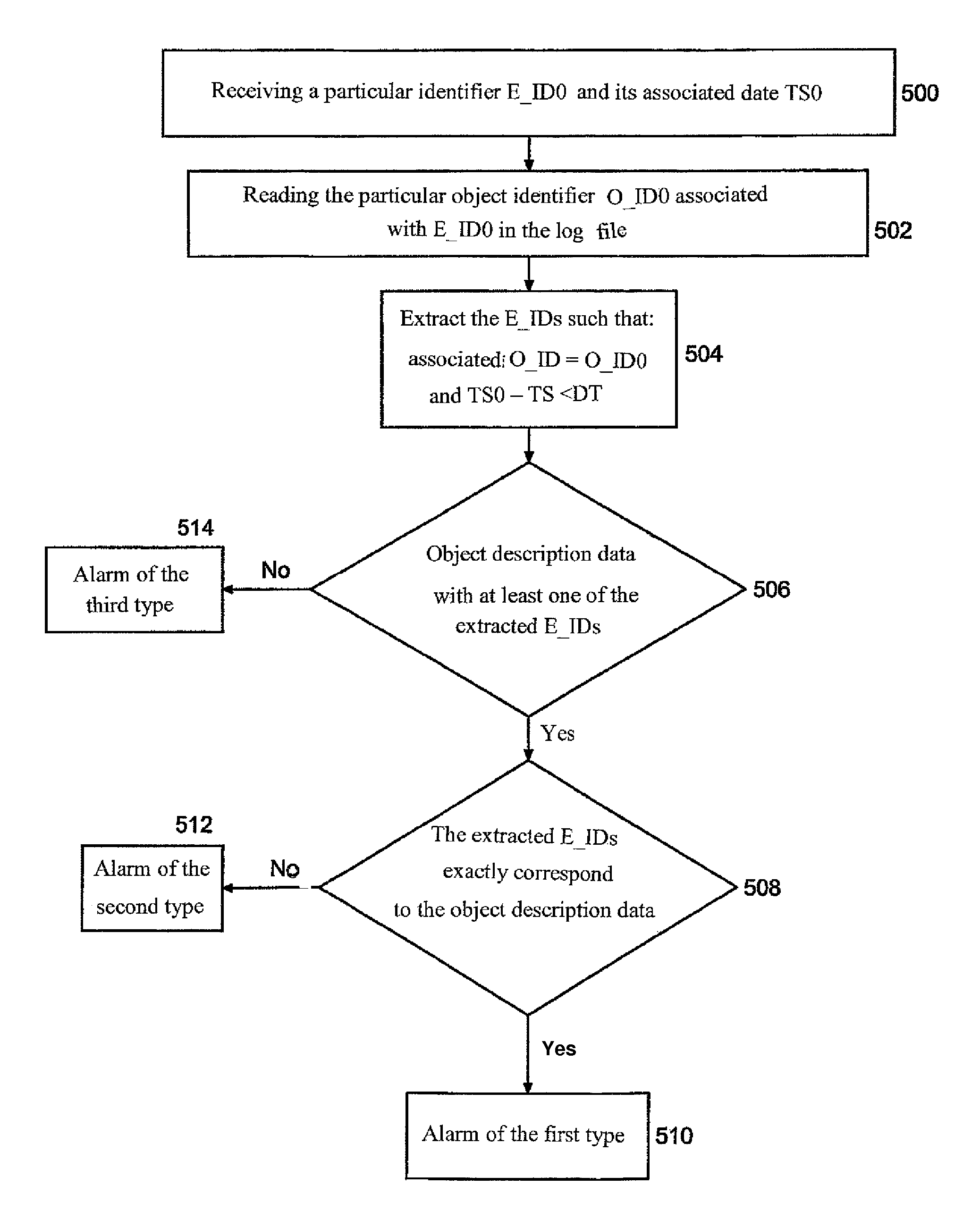
[0096]FIG. 4 illustrates the operation of the controller 15 in this embodiment.

[0097]In step 400, the LECT function and the label reader 13 co-operate for reading a particular label 5, located by means of its individual identifier E_ID. A reading date TS which has the value of the current date TN, is associated with the data extracted from this label.

[0098]In step 402, the controller 15 is laid out so as to ca...

second embodiment

[0116] the LECT function and the label reader 13 are laid out together so as to read labels 5 sequentially and determine a direction of displacement of the label read. For example, the label reader 13 appears as a gantry with at least two antennas, the direction of displacement of a label 5 then being determined by knowing which one of the two antennas has first read the relevant label 5. The label reader 13 may also have a single antenna and be provided with an additional device for detecting the displacement direction, for example of the radar type, capable of establishing whether a label is moving away from or moving closer to it.

[0117]For description purposes, it is considered that the label reader 13 and the LECT function are capable here of determining two opposite displacement directions respectively noted as AB and BA.

[0118]The recording table here assumes the form of two log files grouping the individual E_ID identifiers of the labels 5 read, the data associated with these ...


PUM


Abstract

The invention relates to a device for monitoring physical objects that comprises one or more short-range remote readers (13), memory elements (5) to be attached to physical objects, and a controller (15) adapted for executing a reading function capable of interaction with the one or more remote readers in order to acquire data contained in adjacent memory elements, and for executing an integrity validation function capable of distinguishing, from the acquired data, individual identifiers particular to each of the memory elements as well as group description data stored in at least some of said memory elements, and of checking the sufficiency of group description data while checking the compliance of individual identifiers with corresponding group description data.

Description

RELATED APPLICATIONS[0001]This application is a U.S. National Phase of International Application No.: PCT / FR2009 / 000597, filed May 20, 2009, designating the U.S. and published on Dec. 23, 2009 as WO2009 / 153435A2, which claims the benefit of French Application No. 0802783, filed May 22, 2008 and French Application No. 0901064, filed Mar. 9, 2009.FIELD OF THE INVENTION[0002]The invention relates to a device for monitoring physical objects.BACKGROUND OF THE INVENTION[0003]A large number of situations require monitoring of physical objects.[0004]For example, a very widespread fear of travelers, regardless of their transportation means, is to lose or forget part of their luggage, or further having part of the latter stolen or substituted.[0005]Presently, there are very few solutions for reassuring the traveler, and none of them is satisfactory in practice.[0006]Labelling of the luggage for example is only efficient if a check of the association of the luggage and of their owner is perman...

Claims


Application Information

Patent Timeline
Patent Type & Authority Patents(United States)
IPC IPC(8): G06F7/00G08B13/14G06F17/30H04W4/80
CPCG08B13/14G06Q10/087G08B13/1427H04L63/123H04W4/80H04W12/10H04W12/76G06K7/10366H04W12/04
Inventor BANATRE, MICHELCOUDERC, PAULBECUS, MATHIEUALLARD, FABIEN
Owner INRIA NATIONAL INSTITUTE FOR RESEARCH IN COMPUTER SCIENCE AND CONTROL
Features
  • R&D
  • Intellectual Property
  • Life Sciences
  • Materials
  • Tech Scout
  • Unparalleled Data Quality
  • Higher Quality Content
  • 60% Fewer Hallucinations
Learn More