Coreless transformer UV light source system

Inactive Publication Date: 2016-05-10
DIVERSIFIED TECH INC
View PDF4 Cites 2 Cited by
  • Summary
  • Abstract
  • Description
  • Claims
  • Application Information

AI Technical Summary

Benefits of technology

[0005]This invention features a coreless transformer ultra-violet (UV) light source system comprising a bulb which includes a predetermined amount of an element which efficiently emits UV light when exposed to a high current plasma state and a predetermined amount of a buffer gas therein. An optically thin mesh primary sur

Problems solved by technology

One problem with conventional UV lamps is the magnetic coupling core surrounding the bulb, which blocks the UV light.
Another problem with conventional UV lamps is that since more power is needed to create more UV light, the size of the transformer increases with the desired light output.
This results in large, lossy light blocking magnetic cores.
Such cores may

Method used


Image

  • Coreless transformer UV light source system
  • Coreless transformer UV light source system
  • Coreless transformer UV light source system

Examples


Embodiment Construction

[0015]Aside from the preferred embodiment or embodiments disclosed below, this invention is capable of other embodiments and of being practiced or being carried out in various ways. Thus, it is to be understood that the invention is not limited in its application to the details of construction and the arrangements of components set forth in the following description or illustrated in the drawings. If only one embodiment is described herein, the claims hereof are not to be limited to that embodiment. Moreover, the claims hereof are not to be read restrictively unless there is clear and convincing evidence manifesting a certain exclusion, restriction, or disclaimer.

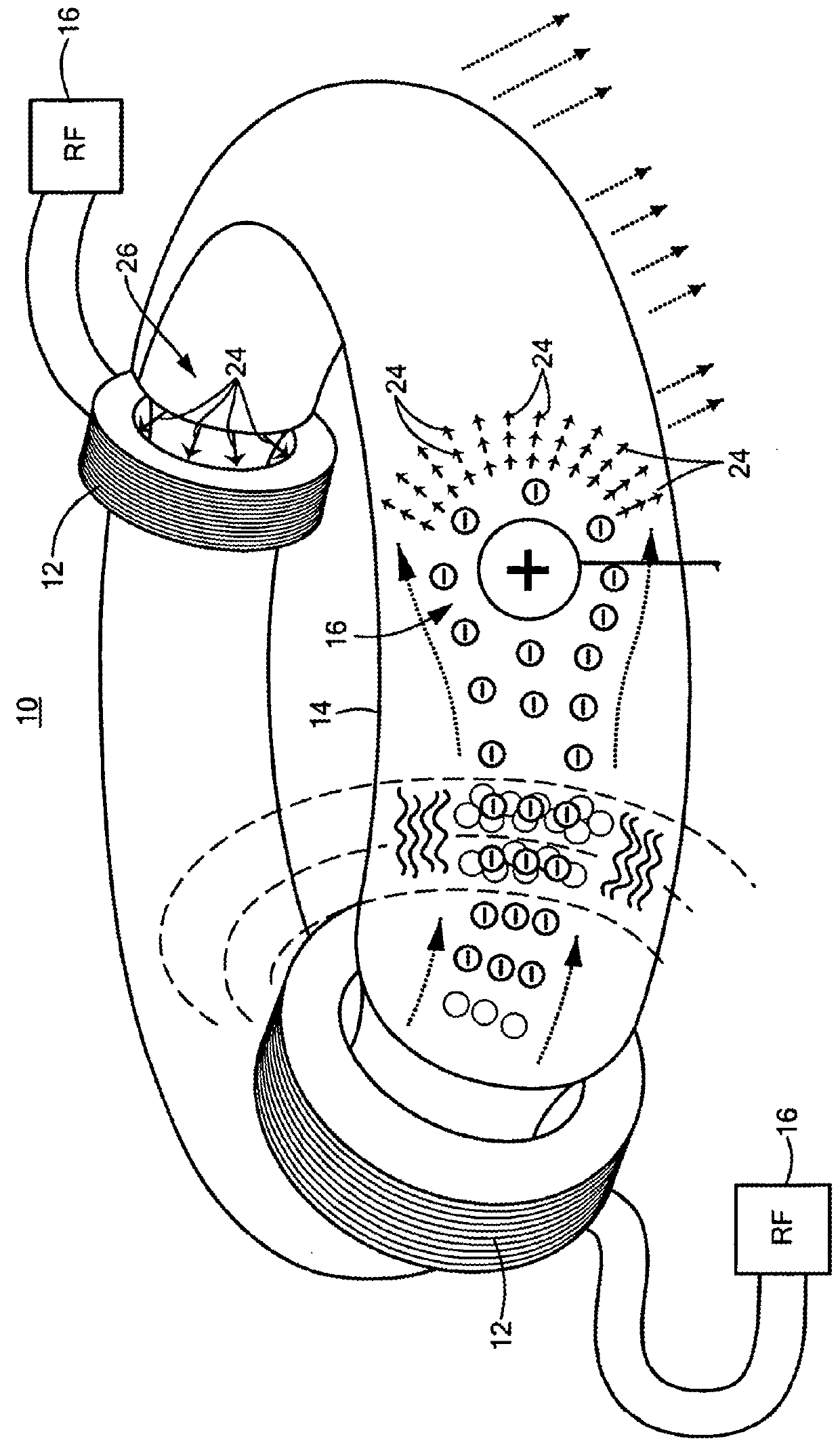
[0016]As discussed in the Background section above, one conventional UV light source 10, FIG. 1, relies on one or more magnetic primary cores or coils 12 which surround bulb 14. RF source 16 drives primary cores 12 and causes them to induce a high electron current inside bulb 14 which creates a plasma state inside bulb 14. ...


PUM


Abstract

A coreless transformer ultra-violet (UV) light source system comprising a bulb including a predetermined amount of an element which efficiently emits UV light when exposed to a high current plasma state and a predetermined amount of a buffer gas therein. An optically thin mesh primary surrounds a portion of the bulb. A pulsed radio frequency (RF) oscillator is coupled to the primary configured to drive high current pulses into the primary causing the light emitting element to form a conducting secondary comprised of the element in a plasma state thereby causing the element to efficiently emit UV light.

Description


Claims


Application Information

Patent Timeline
Owner DIVERSIFIED TECH INC
Why Eureka
Try Eureka