Unlock instant, AI-driven research and patent intelligence for your innovation.

Wire electric discharge machine performing turning tool machining, turning tool machining method with wire electric discharge machine, and program creation apparatus for wire electric discharge machine that performs turning tool machining

a wire electric discharge machine and turning tool technology, which is applied in the direction of electric controllers, programs, instruments, etc., can solve the problems of affecting the shape accuracy of an object to be machined, the tip is difficult to fix in an ideal position on the design without any error, and the rake face is often wavy, etc., to achieve high precision and easy to use

Active Publication Date: 2016-06-14
FANUC LTD
View PDF22 Cites 6 Cited by
  • Summary
  • Abstract
  • Description
  • Claims
  • Application Information

AI Technical Summary

Benefits of technology

This approach enables the production of highly precise and easy-to-use turning tools by accurately measuring and correcting the machining trajectory, reducing errors and simplifying the machining process, thereby improving the shape accuracy and usability of the tools.

Problems solved by technology

In a brazing process, a tip is positioned and fixed in a manner to interpose melted wax, so that it is hard to fix the tip on an ideal position on design without any error.
Further, due to an effect of heat in brazing and unevenness of the thickness of a tip itself, waviness is frequently formed on a rake face.
In a case where the shape of a rake face is different from an ideal shape, when a machining route prepared on the basis of an ideal shape is used as it is, an error in a height direction of an actual rake face with respect to an ideal rake face adversely affects shape accuracy of an object to be machined, generating an error that is unignorable in producing of a highly-precise object.
Further, in a case where “waviness” is formed on a rake face, an error cannot be completely eliminated even by adjusting inclination of the rake face, generating an error on a machined blade.
Therefore, when the tip is actually fixed on a lathe or the like and used, such complicated operation that the tip is fixed on a tool rest with the reference face thereof inclined is required, in a similar manner to turning tool machining, and similar adjustment is required every time a turning tool is exchanged.
Thus, in the conventional machining method, the number of processes is increased in both of manufacturing and a use of a turning tool, and it is hard to produce a precise blade depending on a property of a rake face.

Method used


Image

  • Wire electric discharge machine performing turning tool machining, turning tool machining method with wire electric discharge machine, and program creation apparatus for wire electric discharge machine that performs turning tool machining
  • Wire electric discharge machine performing turning tool machining, turning tool machining method with wire electric discharge machine, and program creation apparatus for wire electric discharge machine that performs turning tool machining
  • Wire electric discharge machine performing turning tool machining, turning tool machining method with wire electric discharge machine, and program creation apparatus for wire electric discharge machine that performs turning tool machining

Examples


Embodiment Construction

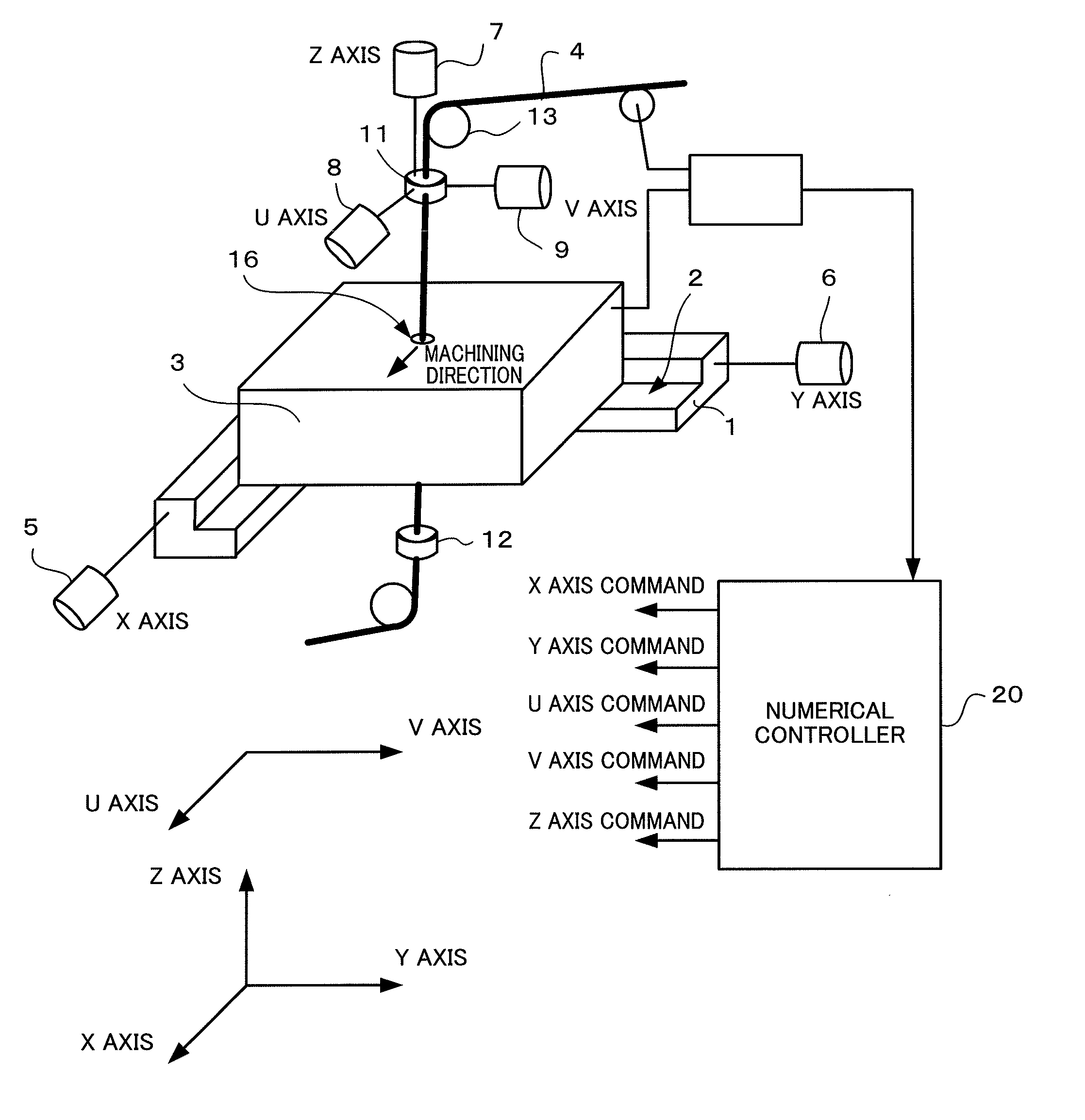
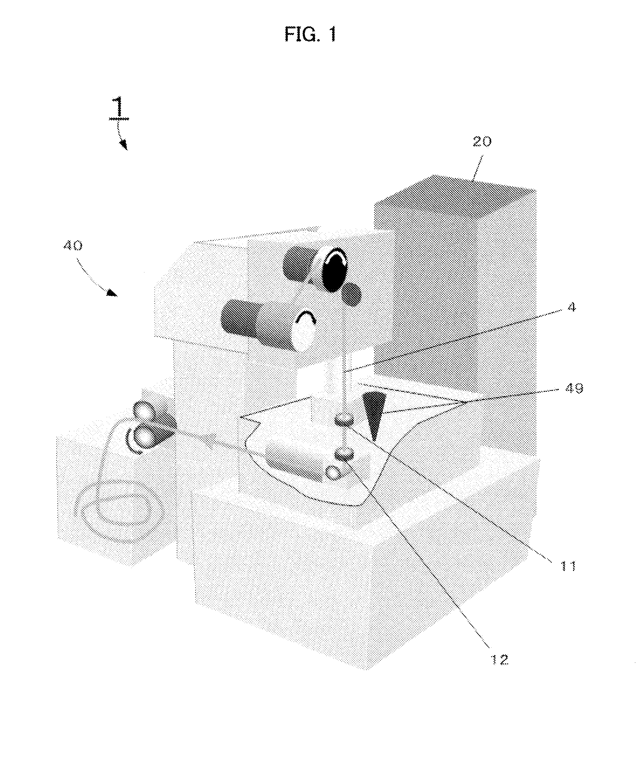
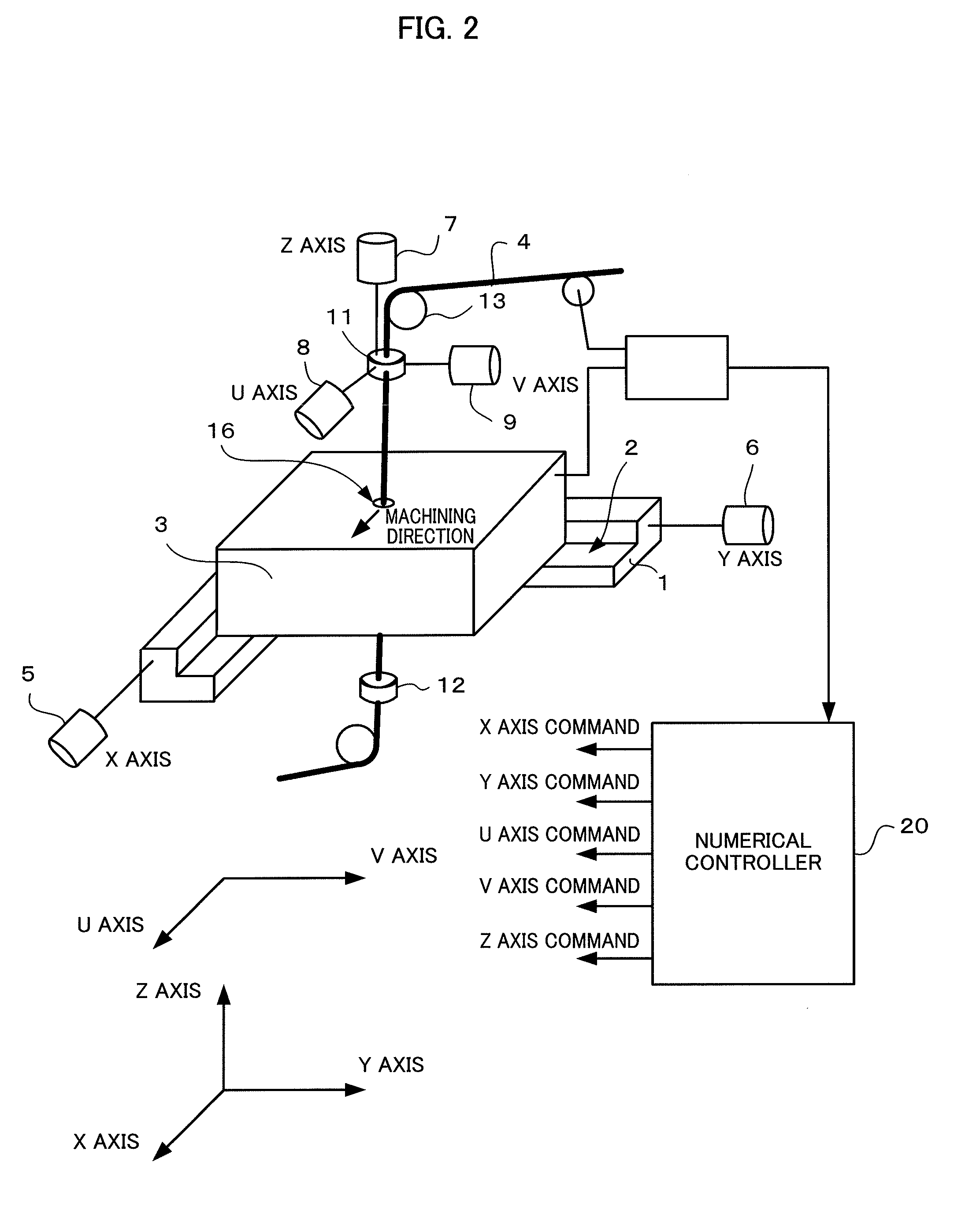
[0033]FIG. 1 is a schematic view illustrating a wire electric discharge machine according to the present invention. A wire electric discharge machine includes a wire electric discharge machine body 40 and a numerical controller 20 which controls the wire electric discharge machine body 40. A wire electrode 4 is stretched between upper and lower wire guides 11 and 12.

[0034]A touch sensor 49 is attached on an upper wire guide part. The touch sensor 49 is attached in parallel with a traveling direction of a wire electrode 4 to be able to be moved vertically by an advancing and retracting mechanism (not depicted), and outputs a signal for detecting contact when the touch sensor 49 is brought into contact with a measuring object. The touch sensor 49 is pulled up to a retracting position at time other than measurement. This touch sensor 49 is used as a measurement unit to measure the height from a reference face on a plurality of points on a route of a machining program, so as to acquire ...


PUM

PropertyMeasurementUnit
angleaaaaaaaaaa
angleaaaaaaaaaa
heightaaaaaaaaaa

Abstract

A measurement program for sequentially measuring measurement points, which are to be measured with a touch sensor, is created on the basis of a machining program, which is read in, for machining a turning tool. Then, the rake face height is measured on each of the measurement points and the measurement data is stored. Subsequently, a calculation method of a correction amount is selected so as to calculate the correction amount, and whether or not the calculated correction amount is smaller than a regulation value is determined. The machining program is modified on the basis of the correction amount when the correction amount is not smaller than the regulation value, while the machining program is modified on the basis of the correction amount in accordance with the selected method when the correction amount is smaller than the regulation value.

Description

RELATED APPLICATIONS[0001]The present application claims priority from Japanese Application No. 2012-027209 filed Feb. 10, 2012, the disclosure of which hereby incorporated by reference herein in its entirety.BACKGROUND OF THE INVENTION[0002]1. Field of the Invention[0003]The present invention relates to a wire electric discharge machine performing turning tool machining, a turning tool machining method with a wire electric discharge machine, and a program creation apparatus for a wire electric discharge machine that performs turning tool machining.[0004]2. Description of the Related Art[0005]Cases of machining a turning tool with a wire electric discharge machine have been increased in recent years (refer to Japanese Patent Application Laid-Open No. 9-267219). Especially, an object to be machined made of a hard material such as a polycrystalline diamond (PCD) tool and a polycrystalline cubic boron nitride (PCBN) tool can discharge electricity so as to be able to be machined in high...

Claims


Application Information

Patent Timeline
Patent Type & Authority Patents(United States)
IPC IPC(8): G05B11/01B23H9/00B23H7/06B23H7/20G05B19/402
CPCB23H7/065B23H7/20B23H9/00G05B19/402G05B11/01B23H2500/20G05B2219/45221G05B19/05B23H1/02
Inventor YAMANE, HIKARUARAKAWA, YASUO
Owner FANUC LTD