Scanning clip

a clip and bar hook technology, applied in the field of scanning bar hooks, can solve the problems of attracting the attention of store surveillance staff, and achieve the effect of making theft more difficul

Active Publication Date: 2016-07-12
PONGRAC IVAN +1
View PDF8 Cites 12 Cited by
  • Summary
  • Abstract
  • Description
  • Claims
  • Application Information

AI Technical Summary

Benefits of technology

[0006]The apparatus aspect of this invention provides a scanning bar hook comprising an upper and lower limb the upper limb ending in a crossbar, display means to support a bar code carrier, arrester means to prevent departure of suspended items from the lower limb more than one at a time and means uniting the display and arrester means which pivotally engages the crossbar.
[0012]The effect is to block the feed of items toward the exit end of the hook end to reduce departure to one item per tilt of the display means.

Problems solved by technology

This may attract the attention of store surveillance staff.

Method used


Image

  • Scanning clip
  • Scanning clip
  • Scanning clip

Examples


Embodiment Construction

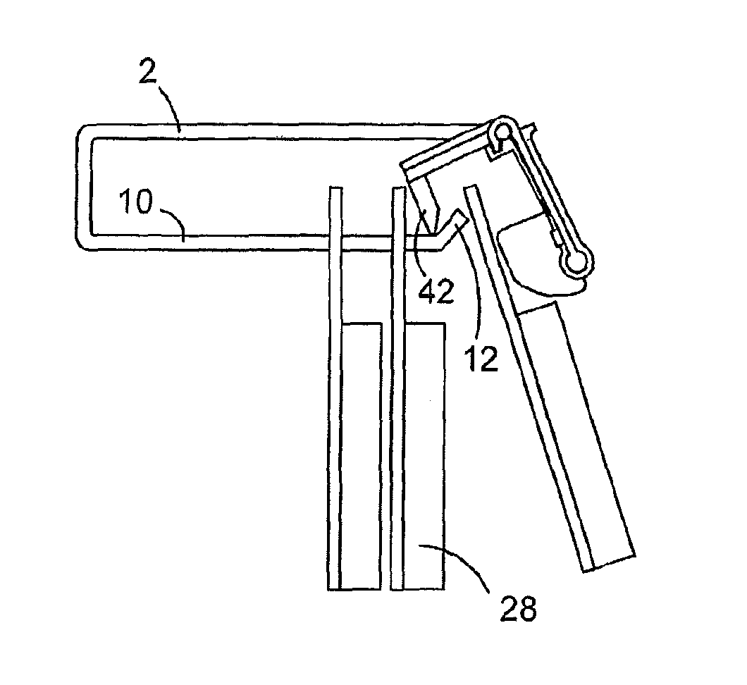
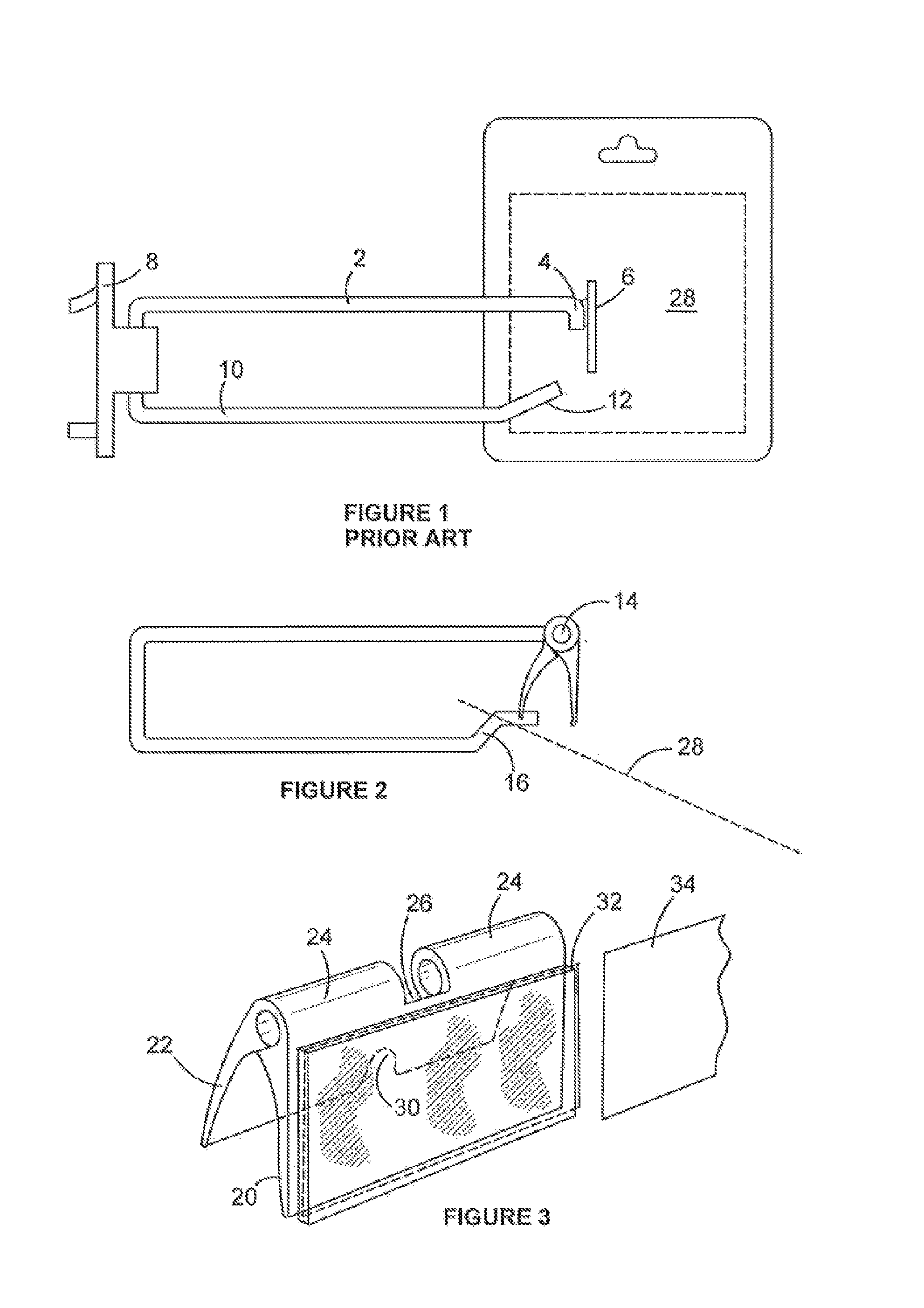
[0025]Referring now to FIG. 1, the upper limb 2 of the hook terminates in a downward bend 4 to which is welded thin plate 6. A transparent plastic envelope (not shown) is fixed to the plate's front face. The pegboard plate 8 holds the mid section of the hook and the lower limb 10 ends in an inclined portion 12.

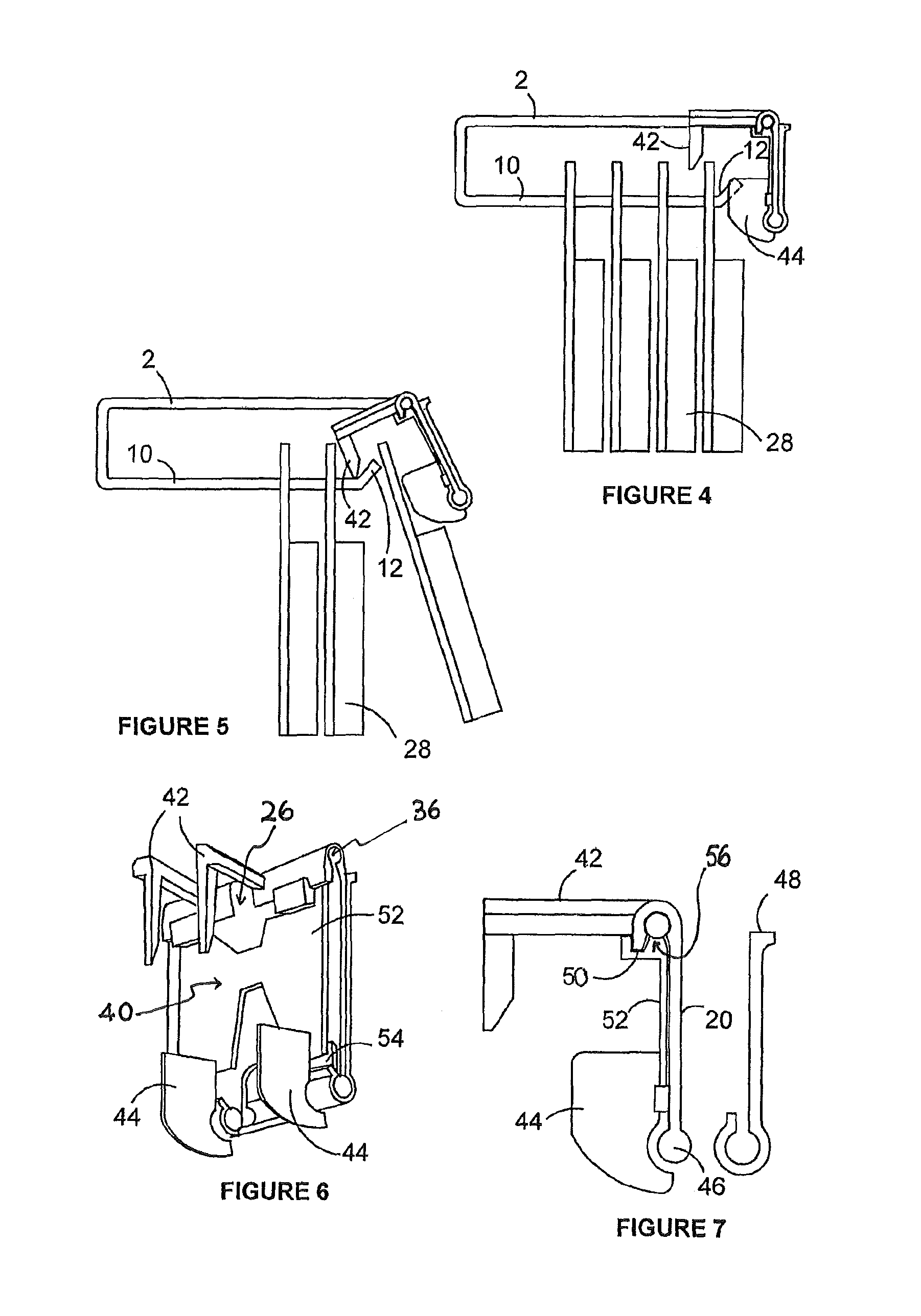
[0026]In FIG. 2 upper limb 2 terminates in crossbar 14 and lower limb ends in crank 16. Upper limb is 360 mm long, while the lower limb is 340 mm long. Crossbar14 is 70 mm long. The anti-theft device in FIG. 3 is a polyethene moulding having a display flap 20 joined to an arrester flap 22. At the confluence of the flaps is a pair of hinge pockets 24 separated by gap 26, the purpose of which is to accommodate the end of upper limb 2.

[0027]The thickness of flaps 20 and 22 increases toward the pockets 24 in order to render it difficult for a thief to remove it from the crossbar 14 on which it is a snap fit.

[0028]The angle between the flaps is about 40 degrees and the length of th...


PUM


Abstract

A scanning bar hook for displaying packeted items in a shop, has upper and lower limbs with a crossbar extending from the upper limb. A molded plastic assembly pivoted on the crossbar has a display flap for mounting a bar code card, a fin extending from the flap toward the first item and an arrester arm which is insertable between the foremost item and the next item. When the foremost item is advanced for removal it strikes the fin and blocks the removal of all the remaining items.

Description

CROSS-REFERENCE TO RELATED APPLICATIONS[0001]This is the U.S. National Stage of International Application No. PCT / AU2013 / 000932, filed Aug. 23, 2013, which in turn claims the benefit of AU Patent Application No. AU 2012903651, filed Aug. 24, 2012.TECHNICAL FIELD[0002]This invention concerns scanning bar hooks used in retail premises to suspend packeted items such as batteries, cutlery and the like.BACKGROUND[0003]The hooks are carried by a moulded plastic plate which has rear facing pegs for engaging vertical pegboard. The forward extending wire limbs are about 300 mm long. The lower limb ends in an upwardly sloping portion and this prevents suspended packets from falling off the limb. The upper limb ends in a downwardly directed portion which supports a rectangular plate. The plate has a clear plastic envelope for displaying a card showing a bar code and price information.[0004]Such scanning hooks make good use of retail space in that they allow high packing density, are easy to lo...

Claims


Application Information

Patent Timeline
Patent Type & Authority Patents(United States)
IPC IPC(8): A47F1/12A47F5/08
CPCA47F1/128A47F5/0807A47F5/0861A47F5/0869
Inventor PONGRAC, IVANPONGRAC, JOHN
Owner PONGRAC IVAN
Why Eureka
Try Eureka