

Tower construction and a method for erecting the tower construction
a technology of tower construction and concrete, which is applied in the field of concrete tower construction, can solve the problems of difficulty in controlling the quality of concrete and logistics of transporting concrete mixture to the site, and the cost of wind turbine towers has increased over the past years
- Summary
- Abstract
- Description
- Claims
- Application Information
AI Technical Summary
Benefits of technology
Problems solved by technology
Method used
Image

Examples
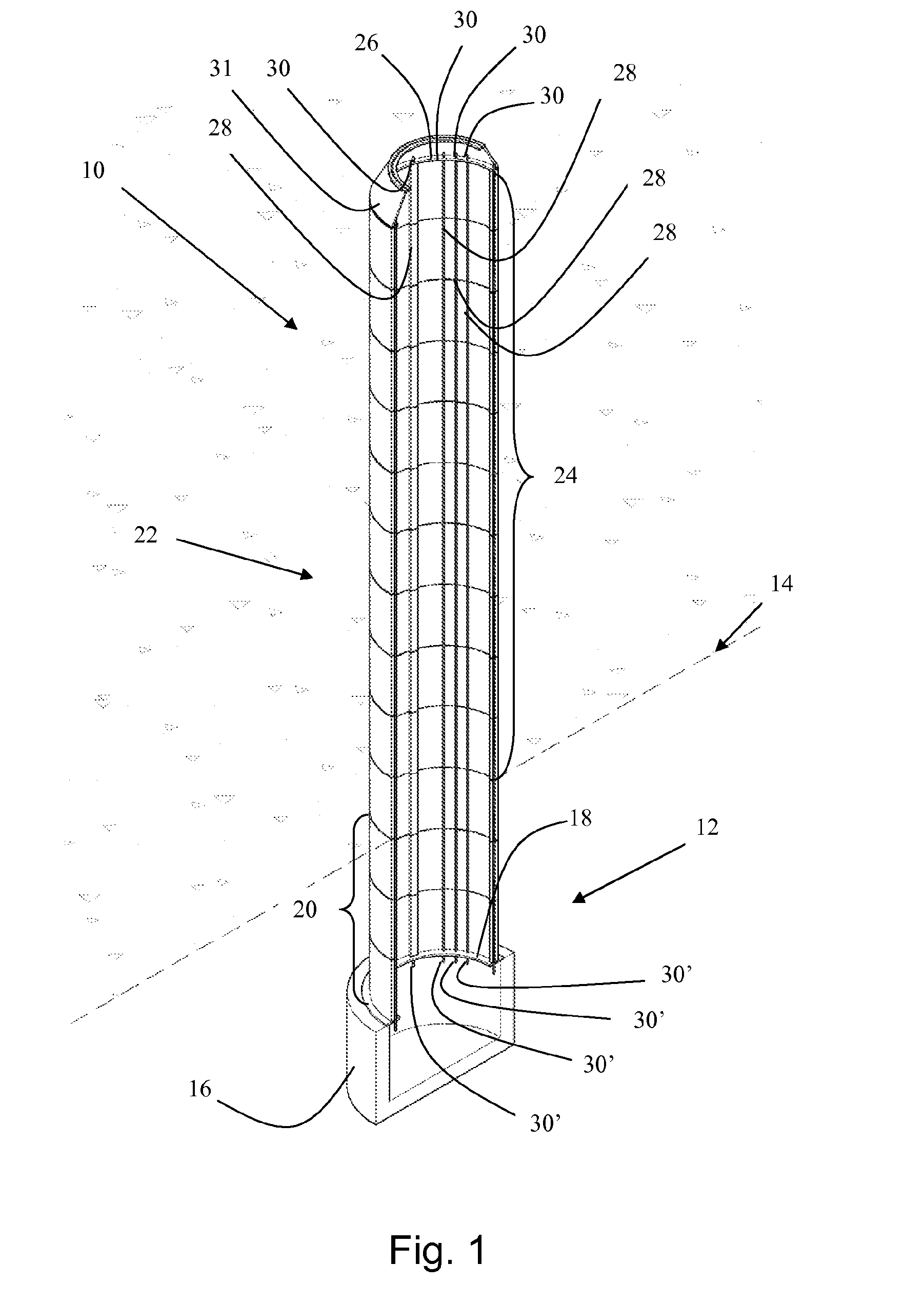
first embodiment
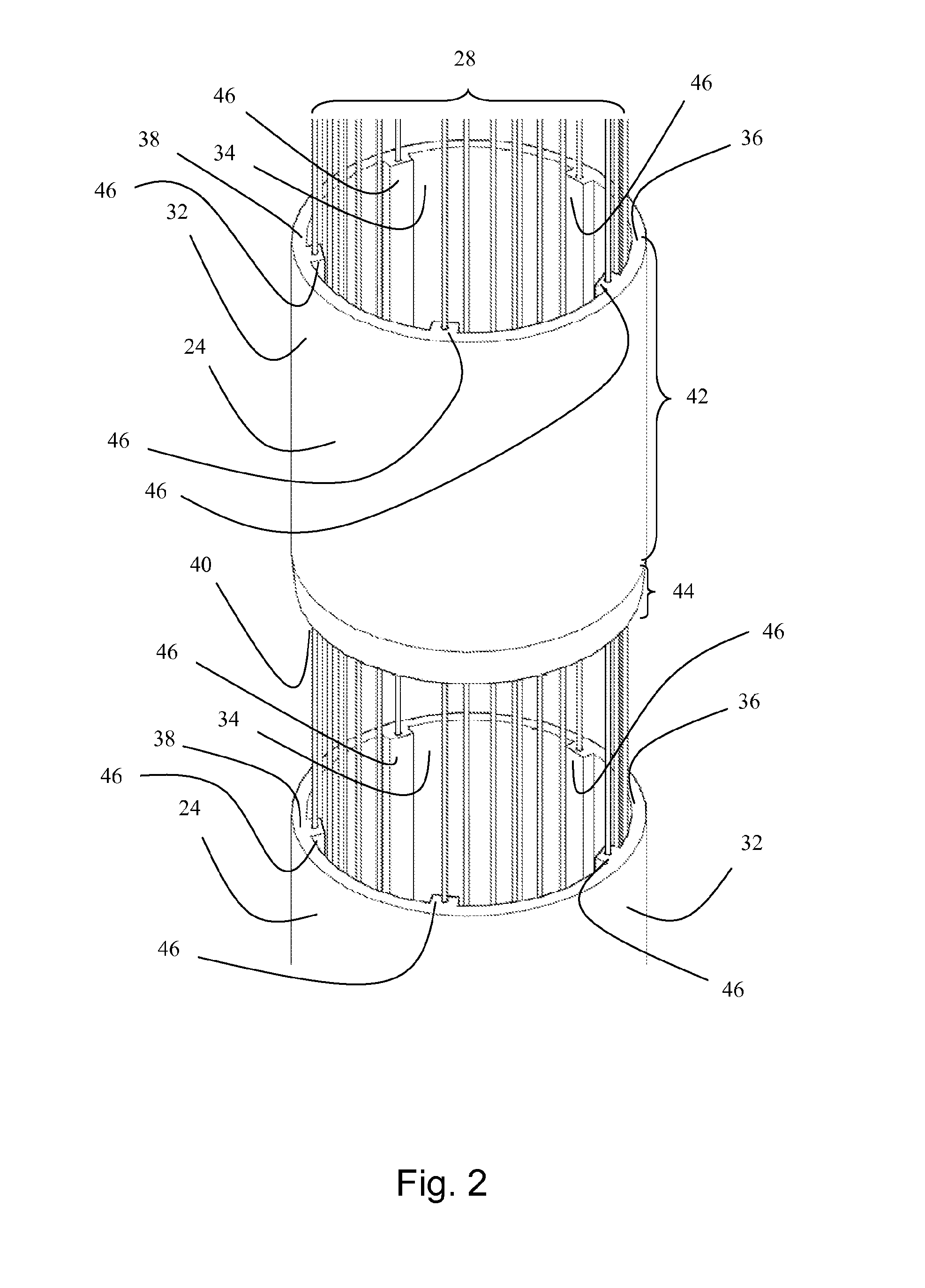
[0163]FIG. 2 shows an exploded view two tower elements of the tower construction according to FIG. 1,
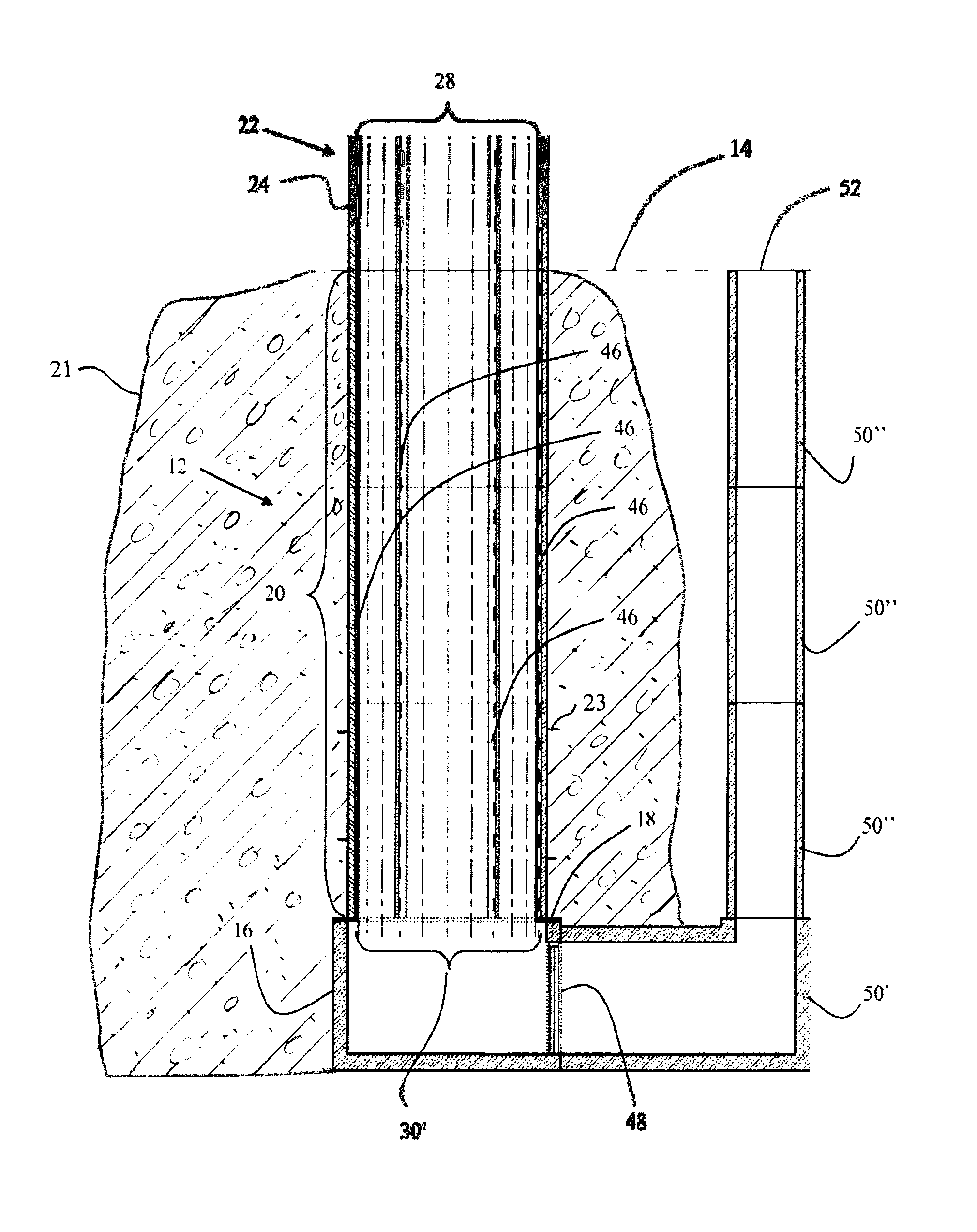
[0164]FIG. 3 shows a cross sectional side view of a foundation of the tower construction according to FIG. 1,
[0165]FIG. 4 shows a cross sectional side view of a foundation of the tower construction according to an alternative embodiment,
[0166]FIG. 5 shows a cross sectional side view of the upper part of the tower construction according to FIG. 1,
[0167]FIG. 6a shows a cross section of a first embodiment of a tower element,
[0168]FIG. 6b shows a section view of a tower element along A-A of FIG. 6a,
second embodiment
[0169]FIG. 7a shows a cross section of a tower element,
[0170]FIG. 7b shows a section view of a tower element along A-A of FIG. 7a,
third embodiment
[0171]FIG. 8 shows an isometric section view of a tower element,
[0172]FIG. 9 shows a plan view of a tower element according to FIG. 8,
PUM
 Abstract
Description
Claims
Application Information