Wheel made out of fiber reinforced material and procedure to make such wheel

a technology of fiber reinforced material and wheel, which is applied in the direction of transportation and packaging, bicycles, other domestic objects, etc., can solve the problems of not offering a failsafe behavior and not sufficiently taking care of thermal stress

Active Publication Date: 2022-11-22
MUBEA CARBO TECH GMBH
View PDF19 Cites 0 Cited by
  • Summary
  • Abstract
  • Description
  • Claims
  • Application Information

AI Technical Summary

Benefits of technology

[0006]The hub of wheels having a rim and wheel center made out of fiber reinforced composite material (composite material) often comprise an insert made from a metallic material which is encompassed by the composite material. During production, the insert is normally arranged in the mold at least partially embedded in the fibers of the reinforced plastic material. It is connected to the composite material when the composite material cures. The hub is important for secure operation of the wheel. It provides the adapter by which the wheel can be connected to an axle of a vehicle. In addition, it prevents contact corrosion and is responsible to transfer large forces between the axle of the vehicle and the rim across the wheel center. Often the known solutions do not sufficiently take care of thermal stress. In addition, they do not offer a failsafe behavior in the case of a faulty condition.
[0007]One aim of the invention is to provide a wheel and a process for making of a wheel that offers an improved transfer of forces during the lifetime of the wheel. The invention further offers the advantage that the impact of the thermal stress can be reduced. In addition, the invention offers the ability that the failsafe behavior of the wheels can be improved.
[0017]If appropriate, the auxiliary body may be used to form at least part of the inside of the hollow spokes and the center opening of the tubular middle section. This offers the advantage to build very lightweight and robust wheels.

Problems solved by technology

Often the known solutions do not sufficiently take care of thermal stress.
In addition, they do not offer a failsafe behavior in the case of a faulty condition.

Method used


Image

  • Wheel made out of fiber reinforced material and procedure to make such wheel
  • Wheel made out of fiber reinforced material and procedure to make such wheel
  • Wheel made out of fiber reinforced material and procedure to make such wheel

Examples


Embodiment Construction

[0040]Reference will now be made in detail to certain embodiments, examples of which are illustrated in the accompanying drawings, in which some, but not all features are shown. Indeed, embodiments disclosed herein may be embodied in many different forms and should not be construed as limited to the embodiments set forth herein; rather, these embodiments are provided so that this disclosure will satisfy applicable legal requirements. Whenever possible, like reference numbers will be used to refer to like components or parts.

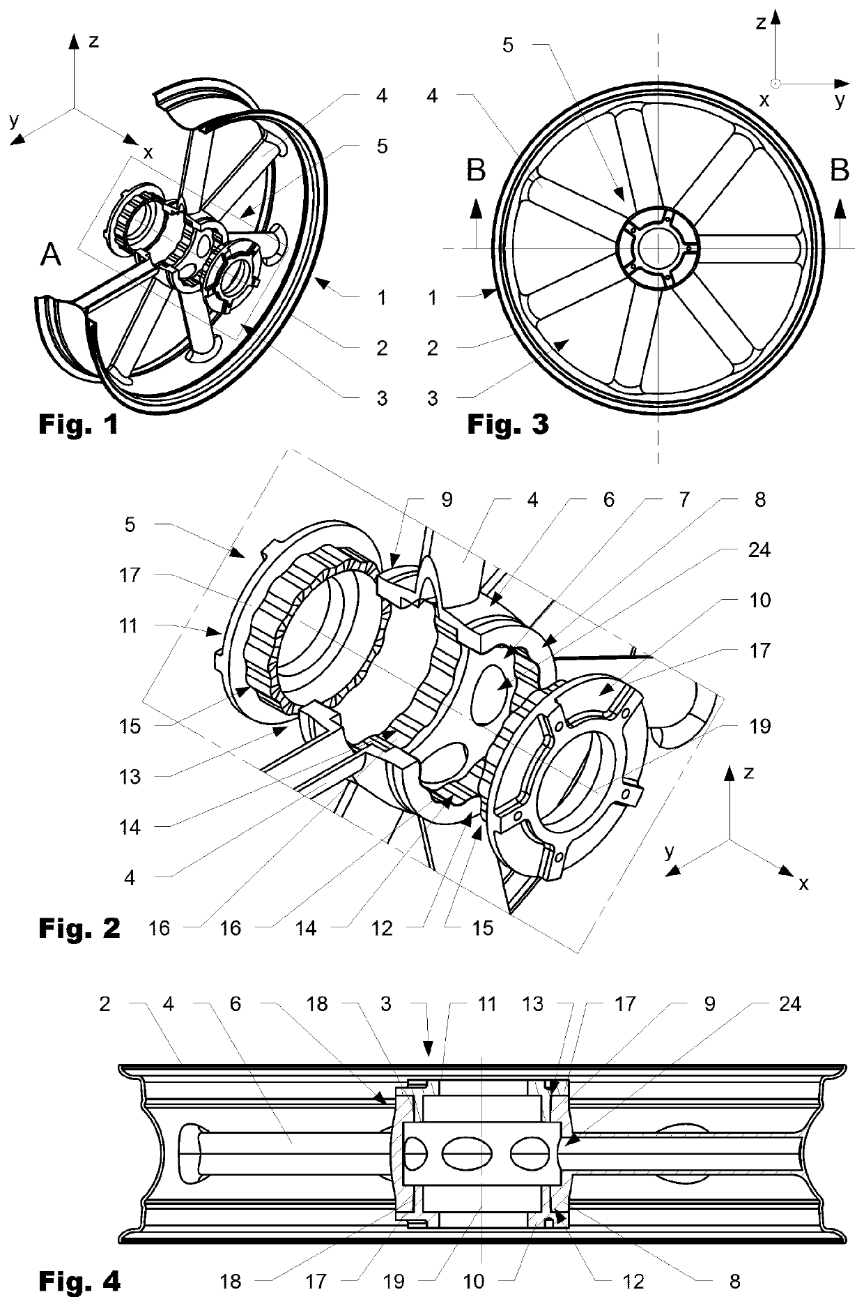
[0041]FIG. 1 is showing a first variation of a wheel 1 according to the invention in a perspective view in a partially cut manner. FIG. 2 is showing detail A of FIG. 1 in a magnified manner. FIG. 3 is showing the wheel 1 in a front view and FIG. 4 is showing section BB of FIG. 3.

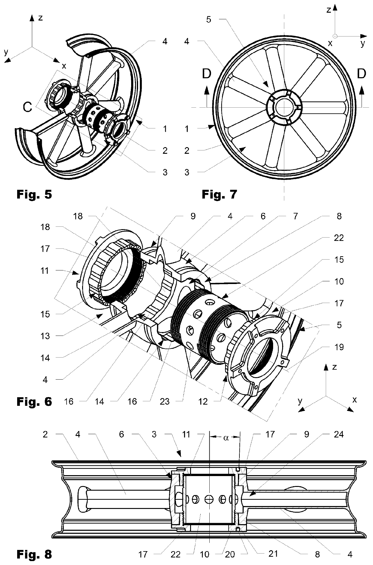
[0042]FIG. 5 is showing a second variation of a wheel 1 according to the invention in a perspective view in a partially cut manner. FIG. 6 is showing detail C of FIG. 5 in a magnified man...


PUM

PropertyMeasurementUnit
taper angleaaaaaaaaaa

Abstract

A wheel (1) includes a rim (2) and a wheel center (3) made from a fiber reinforced composite material. The wheel center (3) includes a tubular middle section (6) having a center opening (7) extending in the direction of a wheel axis (19) and having a first and a second end (8, 9). A hub (5) includes a first flange ring (10) and a second flange ring (11). At least one of the flange rings (10, 11) and the tubular middle section (6) are interconnected to each other by a form fit interconnection (12, 13).

Description

BACKGROUND OF THE INVENTIONField of the Invention[0001]The invention lies in the field of wheels made out of fiber-reinforced material for passenger vehicles such as cars, motorcycles, etc.Discussion of Related Art[0002]WO13083729 published on 22 Aug. 2013 in the name of the same applicant relates to a wheel which comprises a rim and a thereto-connected spoke structure that is made out of fiber reinforced plastic material. An insert is embedded in the fiber-reinforced material at the center of the spoke structure. The insert protrudes in at least one region above the surface of the fiber reinforced plastic material forming at least one contact area.[0003]WO15028337 published on 5 Mar. 2015 in the name of the same applicant relates to a wheel comprising a rim and a wheel center. The wheel center comprises an insert, which comprises a front pad and a rear pad which are a distance apart with respect to each other and which are at least partially embedded in a composite material.[0004]T...

Claims


Application Information

Patent Timeline
Patent Type & Authority Patents(United States)
IPC IPC(8): B60B5/02B60B1/12B60B27/00B29C70/28B29K307/04B29L31/32
CPCB60B5/02B60B1/12B60B27/0073B29C70/28B29K2307/04B29L2031/322B60B2310/204B60B2310/318B60B2310/52B60B2360/341B60Y2200/12B60B25/04Y02T10/86
Inventor RENNER, CHRISTOPH
Owner MUBEA CARBO TECH GMBH
Why Eureka
Try Eureka