Flying Vehicle Guiding System And Flying Vehicle Guiding Method

a flying vehicle and guiding system technology, applied in the direction of vehicle position/course/altitude control, process and machine control, instruments, etc., can solve the problems of inability to fly the uav and cannot be determined by the gps, and achieve the effect of safe operation of the flying vehicle and easy photogrammetry processing

Active Publication Date: 2014-12-18
KK TOPCON
View PDF11 Cites 101 Cited by
  • Summary
  • Abstract
  • Description
  • Claims
  • Application Information

AI Technical Summary

Benefits of technology

[0017]Further, according to the present invention, in the flying vehicle guiding system, the ground base station converts a polar coordinate data from the surveying instrument to an orthogonal coordinate data measured by the GPS unit, and controls the flight of the flying vehicle system based on the orthogonal coordinate data. As a result, flight control of a flying vehicle becomes possible by positional measurement of the surveying instrument using an already existing flying vehicle system where the GPS unit is installed.
[0018]Further, according to the present invention, in the flying vehicle guiding system, the flying vehicle system comprises a camera tiltably supported in an arbitrary direction via a gimbal, and the retro-reflector tilted integrally with the camera and provided in a relation already known with the camera. Thus, it is possible to specify the position of the camera based on the measurement results by the surveying instrument, and the image processing in photogrammetry becomes easy.
[0019]Further, according to the present invention, the flying vehicle guiding method uses a remotely controllable flying vehicle system, and a surveying instrument which can perform a non-prism measurement and a tracking measurement, wherein the flying vehicle guiding method comprises a step of measuring the flight area by non-prism measurement in advance, a step of setting a safe flight area based on the results of preliminary measurement, and a step of remotely controlling the flying vehicle system so as to fly within the safe flight area. As a result, it becomes possible to operate the flying vehicle safely without making contact with an object to be measured or with an obstacle.

Problems solved by technology

However, since a GPS is configured so as to measure a position based on signals given off from a plurality of satellites, at a place where the signals from the satellite cannot be received such as the space between buildings, or in tunnels, etc., the position cannot be determined by the GPS, and it was not possible to fly the UAV.

Method used


Image

  • Flying Vehicle Guiding System And Flying Vehicle Guiding Method
  • Flying Vehicle Guiding System And Flying Vehicle Guiding Method
  • Flying Vehicle Guiding System And Flying Vehicle Guiding Method

Examples


Embodiment Construction

[0032]Description will be given below on embodiments of the present invention by referring to the attached drawings.

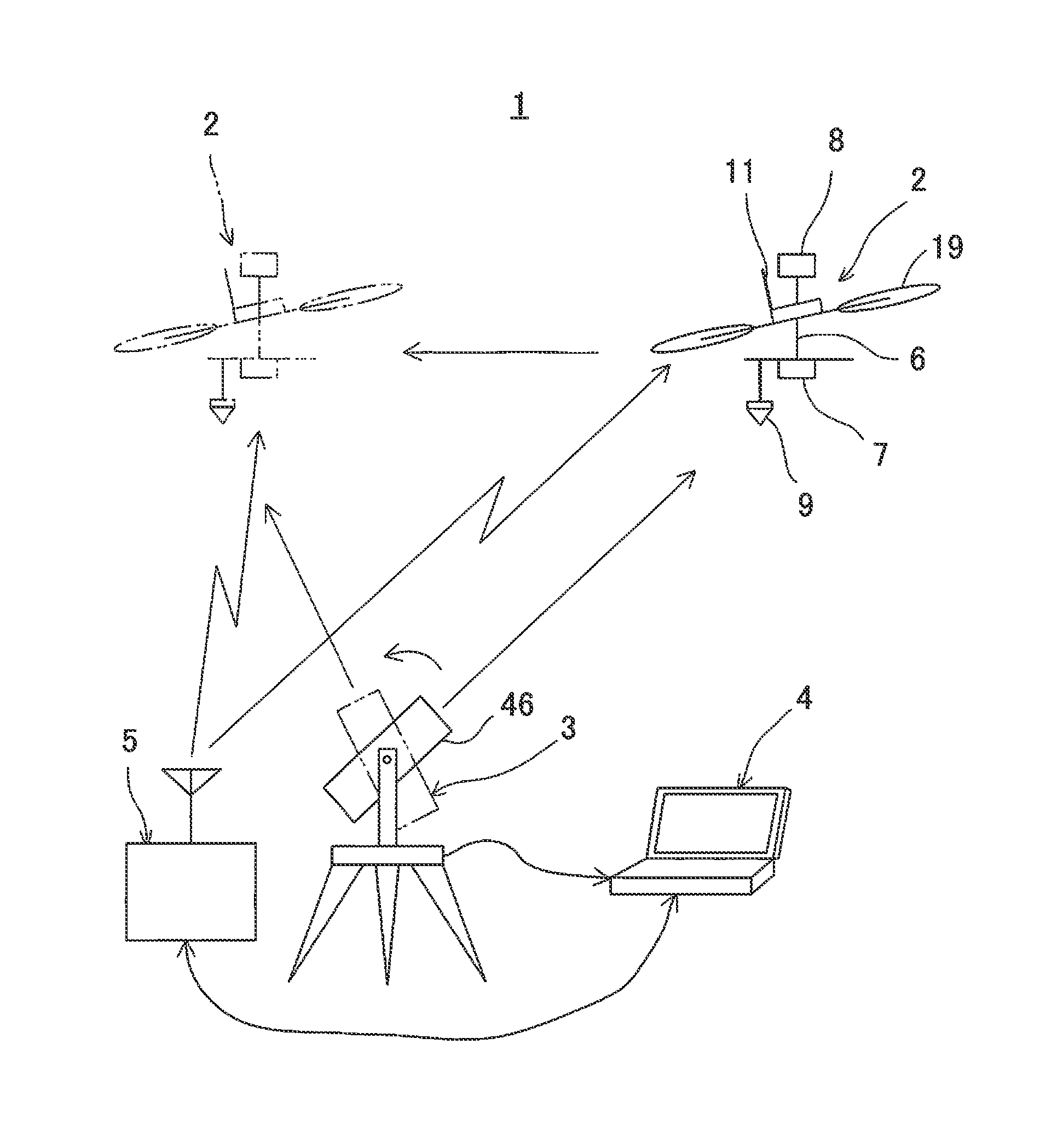
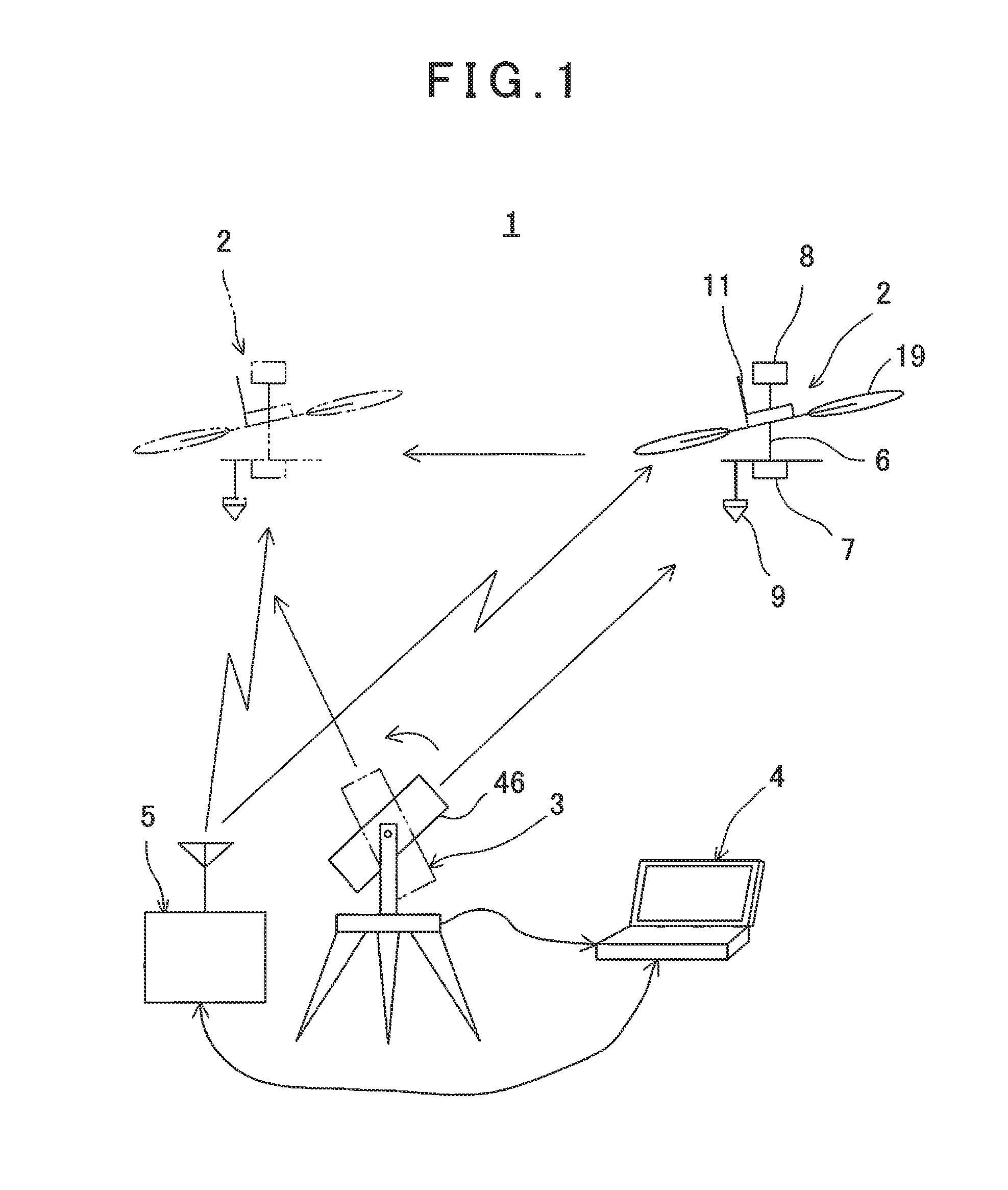
[0033]First, referring to FIG. 1, a description will be given on a flying vehicle guiding system 1 according to the present embodiment.

[0034]The flying vehicle guiding system 1 primarily comprises an air vehicle system (UAV) 2, a surveying instrument 3, a ground base station 4, and a remote controller 5.

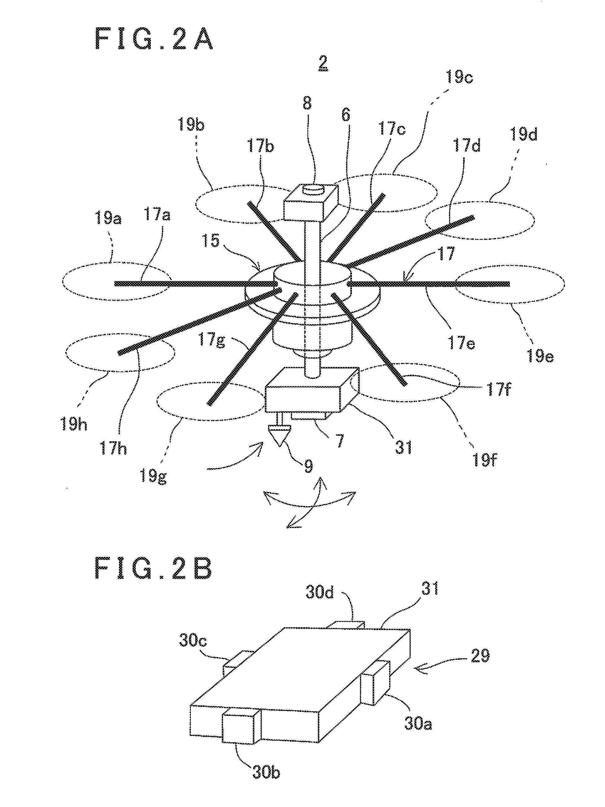
[0035]The flying vehicle system 2 primarily comprises a flying vehicle 15 (to be described later), a shaft 6 as a supporting member vertically supported on the flying vehicle 15 via a gimbal mechanism, a lower camera 7 and an upper camera 8 disposed at a lower end and at an upper end of the shaft 6 respectively, a prism 9 as a retro-reflector installed at a lower end of the shaft 6 integrated with the lower camera 7, and a flying vehicle communication unit 11 to communicate with the ground base station 4. It is to be noted that an optical axis of the lower camera 7 and ...


PUM


Abstract

A flying vehicle guiding system, which comprises a remotely controllable flying vehicle system, a surveying instrument being able to measure distance, angle, and track, and a ground base station for controlling a flight of the flying vehicle system based on measuring results by the surveying instrument, wherein the flying vehicle system has a retro-reflector as an object to be measured, wherein the surveying instrument has a non-prism surveying function for performing distance measurement and angle measurement without a retro-reflector, a prism surveying function for performing distance measurement and angle measurement with respect to the retro-reflector, and a tracking function for tracking the retro-reflector and for performing distance measurement and angle measurement, wherein the surveying instrument performs non-prism measurement on a scheduled flight area, the ground base station sets a safe flight area based on the results of the non-prism measurement, and controls so that the flying vehicle system flies in the safe flight area based on the results of tracking measurement by de surveying instrument.

Description

BACKGROUND OF THE INVENTION[0001]The present invention relates to a flying vehicle guiding system and a flying vehicle guiding method for remote controlling a small type unmanned air vehicle (UAV: Unmanned Air Vehicle).[0002]In recent years, with progress of UAV (Unmanned Air Vehicle), various types of apparatuses are installed on the UAV, and operations as required are performed by remote control or automatic flight. For instance, a camera for photogrammetry is installed on the UAV and a photograph is taken from a high position or at the place where no operator can gain access, and photogrammetry can be carried out by using acquired photographs.[0003]When carrying out a remote control operation, it is necessary to perform measurement at the present position of the UAV in real time, and normally, a GPS (global positioning system) is installed on the UAV, and the position of the UAV is determined by the GPS.[0004]However, since a GPS is configured so as to measure a position based on...

Claims


Application Information

Patent Timeline
Patent Type & Authority Applications(United States)
IPC IPC(8): B64C39/02
CPCB64C39/024G01C11/00G01C15/00G05D1/0094G05D1/106
Inventor OHTOMO, FUMIOKUMAGAI, KAORUOSARAGI, KAZUKIOTANI, HITOSHI
Owner KK TOPCON
Why Eureka
Try Eureka