Single chip multi-function display controller and method of use thereof

a display controller and single chip technology, applied in the field of single chip multi-function display controllers, can solve the problems of increasing the cost and complexity of implementing these various non-control yet essential ancillary display support functions

Active Publication Date: 2008-09-02
GENESIS MICROCHIP
View PDF7 Cites 43 Cited by
  • Summary
  • Abstract
  • Description
  • Claims
  • Application Information

AI Technical Summary

Benefits of technology

[0010]An adaptive scaler unit preserves bandwidth, processing and memory resources by adaptively scaling the input video stream using a scaling protocol based upon a native resolution and a display resolution. In one embodiment, the output interface provides additional image processing such as image enhancement, edge enhancement, contrast enhancement, etc. In one implementation, an optional noise reducer unit is used remove any noise from the image stream.

Problems solved by technology

Currently, most LCD controllers require pixel-based graphical data to be fetched from a memory circuit in a repetitive and cyclical fashion.
Although well suited to actually perform the above described control functions, currently configured LCD controllers rely on other circuits to perform non-LCD control functions such as Frame Rate Conversion (FRC), motion compensation, etc. thereby greatly increasing the cost and complexity of implementing these various non-control yet essential ancillary display support functions.

Method used


Image

  • Single chip multi-function display controller and method of use thereof
  • Single chip multi-function display controller and method of use thereof
  • Single chip multi-function display controller and method of use thereof

Examples


Embodiment Construction

[0017]Reference will now be made in detail to a particular embodiment of the invention an example of which is illustrated in the accompanying drawings. While the invention will be described in conjunction with the particular embodiment, it will be understood that it is not intended to limit the invention to the described embodiment. To the contrary, it is intended to cover alternatives, modifications, and equivalents as may be included within the spirit and scope of the invention as defined by the appended claims.

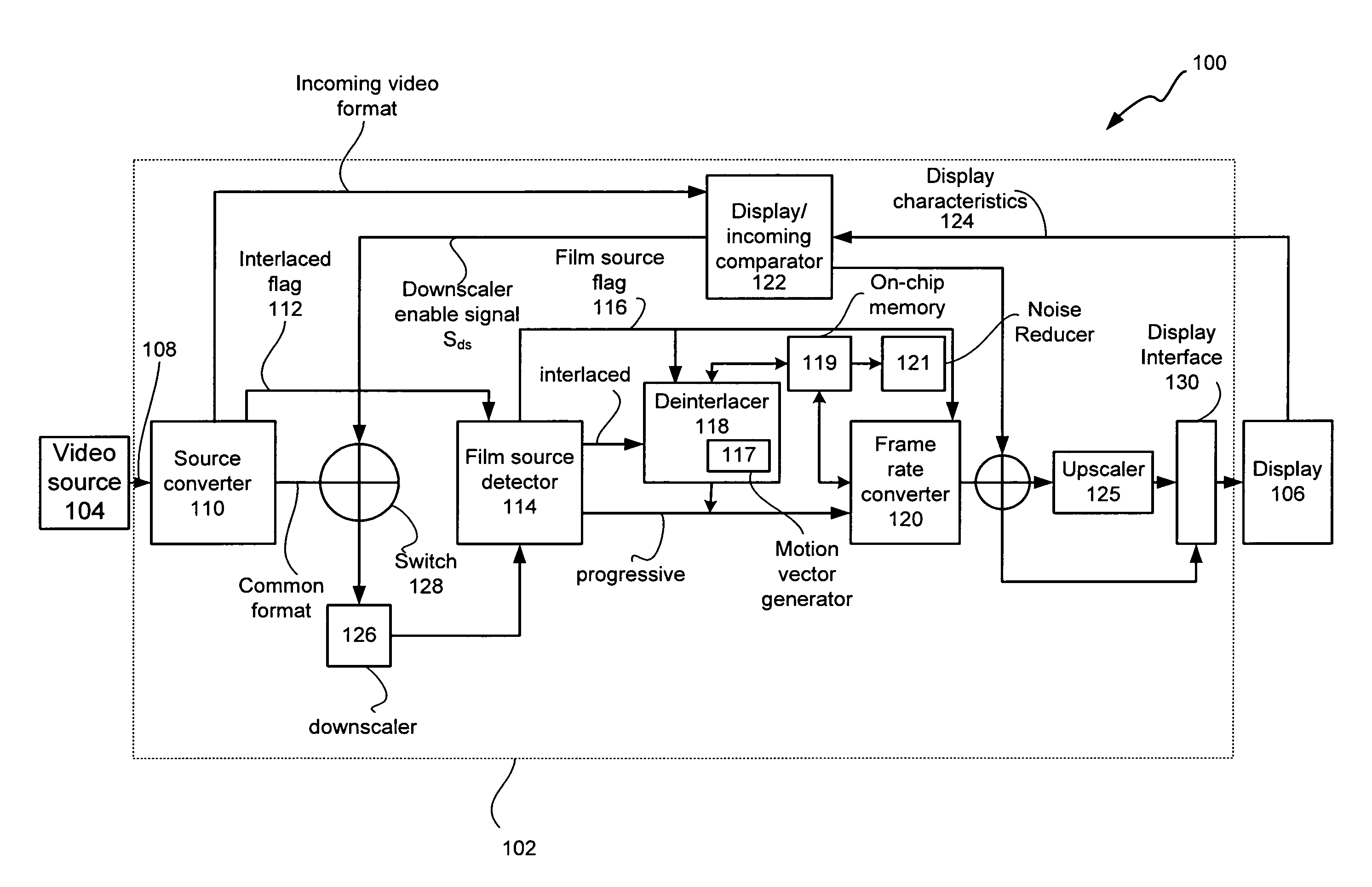
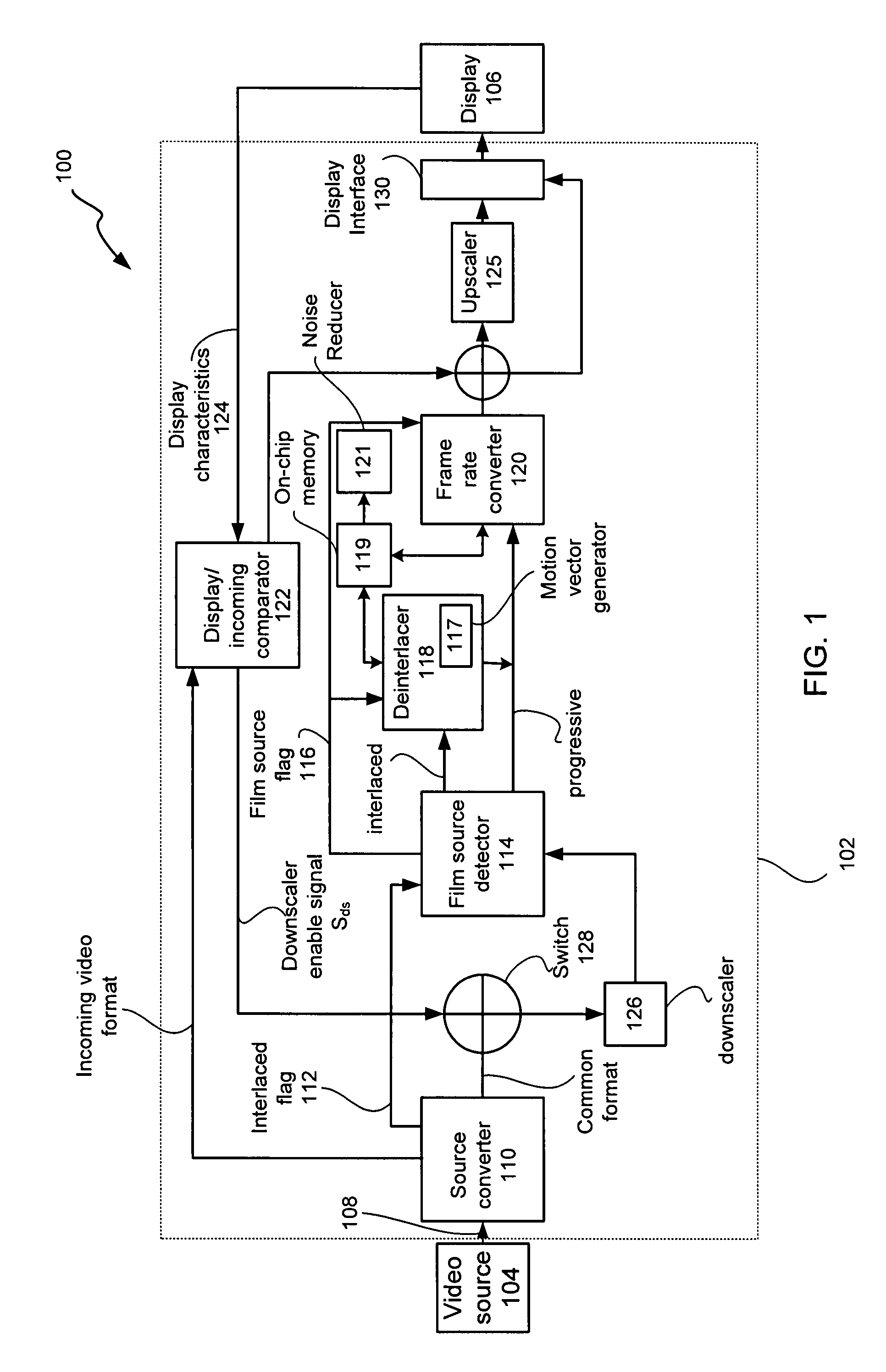
[0018]FIG. 1 shows a general configuration of a system 100 that includes a block diagram representation of a multi-function display controller 102 coupled to a video source 104 and a display 106 in accordance with an embodiment of the invention. It should be noted that the controller 102 is well suited for implementation as a single integrated circuit and as such, can be incorporated in or coupled to the display device 106 (such as an LCD panel). The controller 102 receives...


PUM


Abstract

A multi-function display controller that includes a source detector unit for determining if the source of an input stream is either film originated source originated or video source originated. A source converter unit for converting the input image stream to a common signal processing format is coupled to the source detector unit. Once converted to the common signal processing format, a determination is made if the input image stream is interlaced or non-interlaced (progressive scan). If the input image stream is interlaced, a de-interlace unit converts the interlaced signal to progressive scan using either motion adaptive or motion compensated de-interlacing techniques. It should be noted that in the described embodiment, motion vectors generated for use by the motion compensated de-interlace can be optionally stored in a memory unit for use in subsequent operations, such as motion compensated frame rate conversion or noise reduction (if any).

Description

REFERENCE TO RELATED APPLICATIONS[0001]This patent application takes priority under 35 U.S.C. 119(e) to (i) U.S. Provisional Patent Application No.: 60 / 532,428, filed on Dec. 23, 2003 entitled “Single Chip Integration of Film Mode Detector, 3:2 / 2:2 Inverse Pulldown, Motion Adaptive / Compensated De-interlace, Noise Reducer, Frame Rate Converter, Scaler and Display Controller” which is also incorporated by reference in its entirety for all purposes.BACKGROUND[0002]1. Field of the Invention[0003]The invention relates to display devices. More specifically, the invention describes a multi-function display controller for LCD displays implemented as a single integrated circuit.[0004]2. Overview[0005]LCD displays such as those used on portable, wireless communication devices, digital TVs, and the like are arranged in an x-y grid that is formed by an array of the rows and columns. The arrangement of such segments is done to greatly reduce the number of external connections and increase potent...

Claims


Application Information

Patent Timeline
Patent Type & Authority Patents(United States)
IPC IPC(8): H04N7/01H04N5/46G09G3/36G06T3/40G09G3/20G09G5/00G09G5/18G09G5/36G09G5/391H04N5/208H04N5/21H04N5/44H04N5/66
CPCG06T3/40G09G3/3611H04N7/01H04N7/0112G09G2310/0229H04N7/012G09G2340/0407G09G3/20G09G3/36
Inventor SWARTZ, PETER D.
Owner GENESIS MICROCHIP
Why Eureka
Try Eureka