Neuro-stimulation

a neurostimulation and electrode technology, applied in the field of neurostimulation, can solve problems such as complex heart pacemakers, and achieve the effect of increasing the density of electrodes and controlling the selectivity of stimuli

Active Publication Date: 2012-06-28
SALUDA MEDICAL PTY LTD
View PDF12 Cites 100 Cited by
  • Summary
  • Abstract
  • Description
  • Claims
  • Application Information

AI Technical Summary

Benefits of technology

[0009]Advantageously, the two-wire bus provides flexibility to the system since additional cells can be easily added; likewise cells can be removed. Different types of cells can also be mixed along the length of the bus; for instance sensor cells may be interposed with stimulating cells. The bus also facilitates replacement of the implant controller. Another advantage of the two-wire bus is that the feed-throughs in each electrode cell only require two pins for power and commands, and one more for each electrode. An additional wire could be added to the bus for communications. Any type of wire able to carry data could be used, for instance an optical fibre.
[0016]The control logic in the implant controller or electrode cells, or both, may be provided by a processor or programmable logic array. However, smaller solutions are preferred, for instance involving state machines or simple logic arrays or VLSI chips. The implant controller may have a reference electrode, which in use is in contact with the tissue. The electrode cells may be very small to enable their use in confined spaces, such as the cochlear or spine. Stimulus selectivity may be controlled by increasing the density of electrodes.
[0017]Another advantage of the power signals is that the system may continue to operate safely after a single fault failure, that is, where one of the wires has its insulation breached.
[0031]It should be noted that the electrode cells do not use free-running clocks that consume power when there is no activity. This means selected cells, or even the entire array, can be shut down by removing power; making it fail-safe. In the electrode cells the power consumption of the control logic is proportional to the data rate. Another advantage is that decoding at the cells is insensitive to process variations over a 10:1 range; unlike coding schemes, such as Manchester coding, that require a clock in the receiver.

Problems solved by technology

They are more complex than heart pacemakers and involve an implant controller that contains all the active electronic components, as well as twenty or so passive electrodes individually connected to the controller.

Method used


Image

  • Neuro-stimulation
  • Neuro-stimulation
  • Neuro-stimulation

Examples


Embodiment Construction

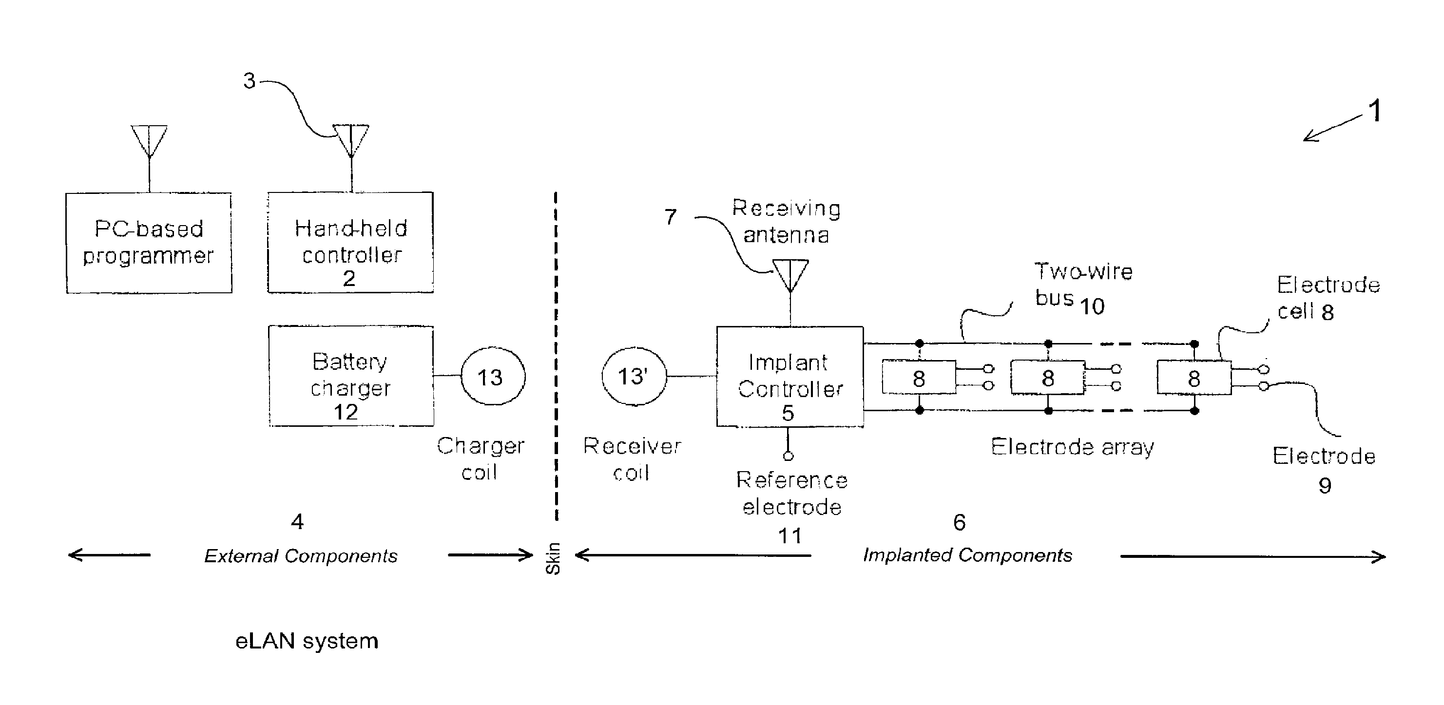
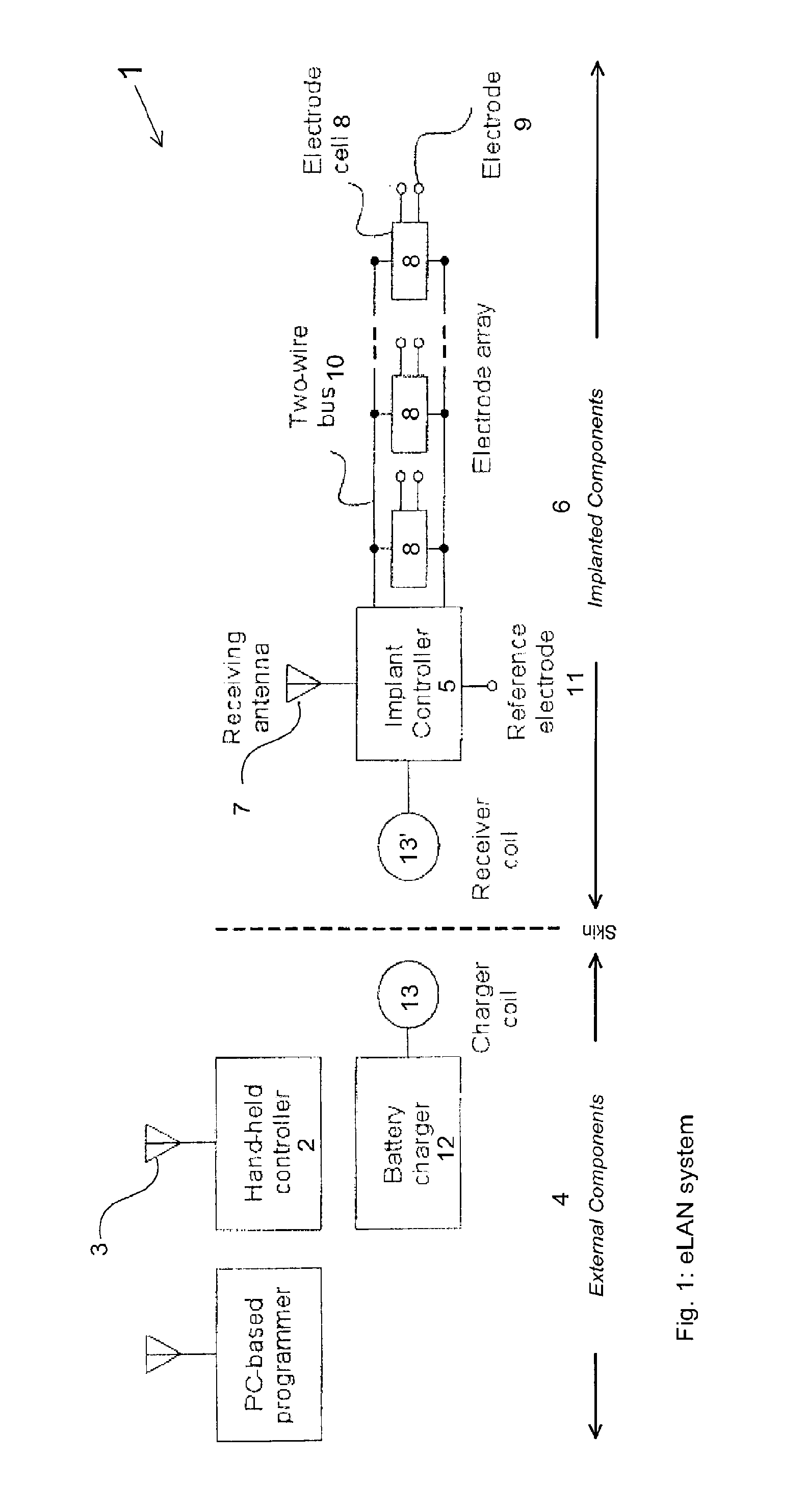
[0052]Referring first to FIG. 1, the implant architecture 1 comprises an external PC based programmer and hand-held controller 2 and a transmitter 3, located outside the body 4. The transmitter 3 communicates with a distributed implantable neuro-stimulation system comprising an implant controller 5, plural electrode cells 8 and an interconnecting two-wire bus 10 in the body 6. The implant controller 5 has a receiver 7 to receive communications from transmitter 3. In general each of the electrode cells 8 has one or more stimulus electrodes 9, and all the electrode cells 8 are connected to the two-wire bus 10 in an identical manner. The two-wire bus 10 is connected back to the implant controller 5. The implant controller also has a reference electrode 11. A battery charger 12 recharges the battery in the implant controller 5 via a charger coil 13 and receiver coil 13′.

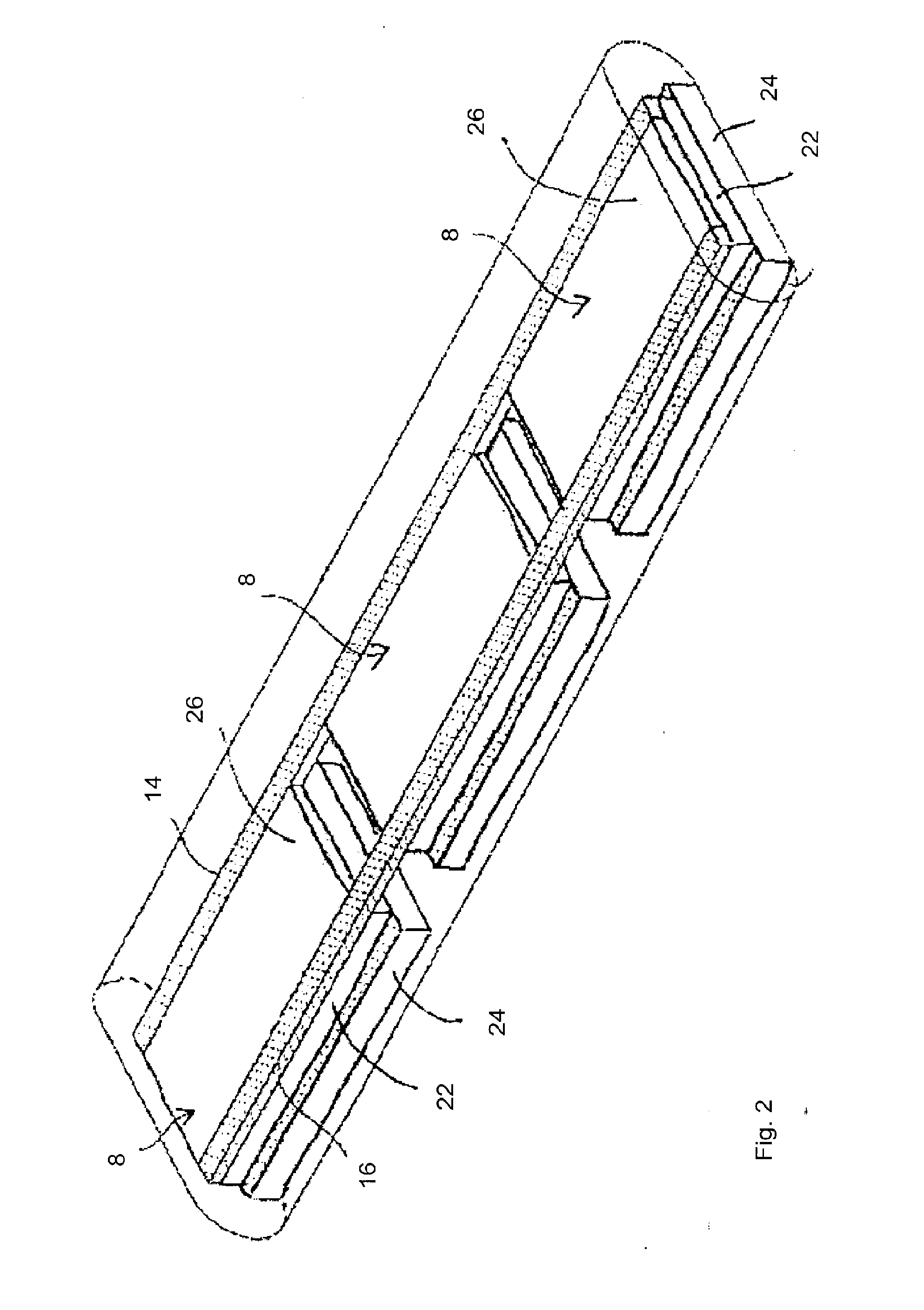
[0053]In general the implant controller 5 and electrode cells 8 have a sealed exterior wall to isolate the interior el...


PUM


Abstract

The invention is a distributed implantable neuro-stimulation system, comprising an implant controller including control logic to transmit two time-varying power signals, varying between two levels and out of phase with the other, and a command signal modulated onto at least one of the power signals. One or more electrode cells, each having control logic to extract charge from the power signals and recover commands from the command signal. A two-wire bus interconnecting the implant controller and all the electrode cells, to carry one of the time varying signals in each of the two wires, and to carry the command signal.

Description

BACKGROUND OF THE INVENTION[0001]1. Field of the Invention[0002]This invention concerns neuro-stimulation, that is artificial electrical stimulation of body tissues using a device implanted in the body. In particular the invention concerns a distributed implantable neuro-stimulation apparatus, an electrode cell forming part of the apparatus, an implant controller forming part of the apparatus, a method of applying neuro-stimulation, and a signal for use in the method.[0003]2. Description of Related Art[0004]Perhaps the pacemaker is the best known tissue stimulator. It is implanted in the chest and a single electrode is connected to the heart to regulate the rate of beating. Cochlear implants are neuro-stimulators used to restore hearing. They are more complex than heart pacemakers and involve an implant controller that contains all the active electronic components, as well as twenty or so passive electrodes individually connected to the controller. The controller is sealed inside a ...

Claims


Application Information

Patent Timeline
Patent Type & Authority Applications(United States)
IPC IPC(8): G08C19/16
CPCA61N1/05A61N1/36189A61N1/36146
Inventor SINGLE, PETERROBINSON, DAVIDPARKER, JOHNAYRE, PETERKARANTONIS, DEAN
Owner SALUDA MEDICAL PTY LTD
Why Eureka
Try Eureka