Surface area deposition trap

a technology of surface area and deposition trap, which is applied in the direction of fluid pressure measurement, variable capacitor, instruments, etc., can solve the problem of increasing the likelihood that a contaminant particle will become stuck to one of the walls

Inactive Publication Date: 2007-08-07
MKS INSTR INC
View PDF37 Cites 137 Cited by
  • Summary
  • Abstract
  • Description
  • Claims
  • Application Information

AI Technical Summary

Benefits of technology

[0013]These and other objects are provided by an improved pressure transducer that includes a deposition trap in the fluid path between an external source of gas or fluid (e.g., gas line or deposition chamber) and the pressure sensor. The deposition trap may be disposed for example in the inlet tube or in a coupling between the inlet tube and the external source. The deposition trap provides a plurality of narrow channels through which material passes prior to reaching the diaphragm. The large number of narrow channels increases the likelihood that a contaminant particle will become stuck to one of the walls of the channels rather than passing through the deposition trap and reaching the pressure sensor.

Problems solved by technology

The large number of narrow channels increases the likelihood that a contaminant particle will become stuck to one of the walls of the channels rather than passing through the deposition trap and reaching the pressure sensor.

Method used


Image

  • Surface area deposition trap
  • Surface area deposition trap
  • Surface area deposition trap

Examples


Embodiment Construction

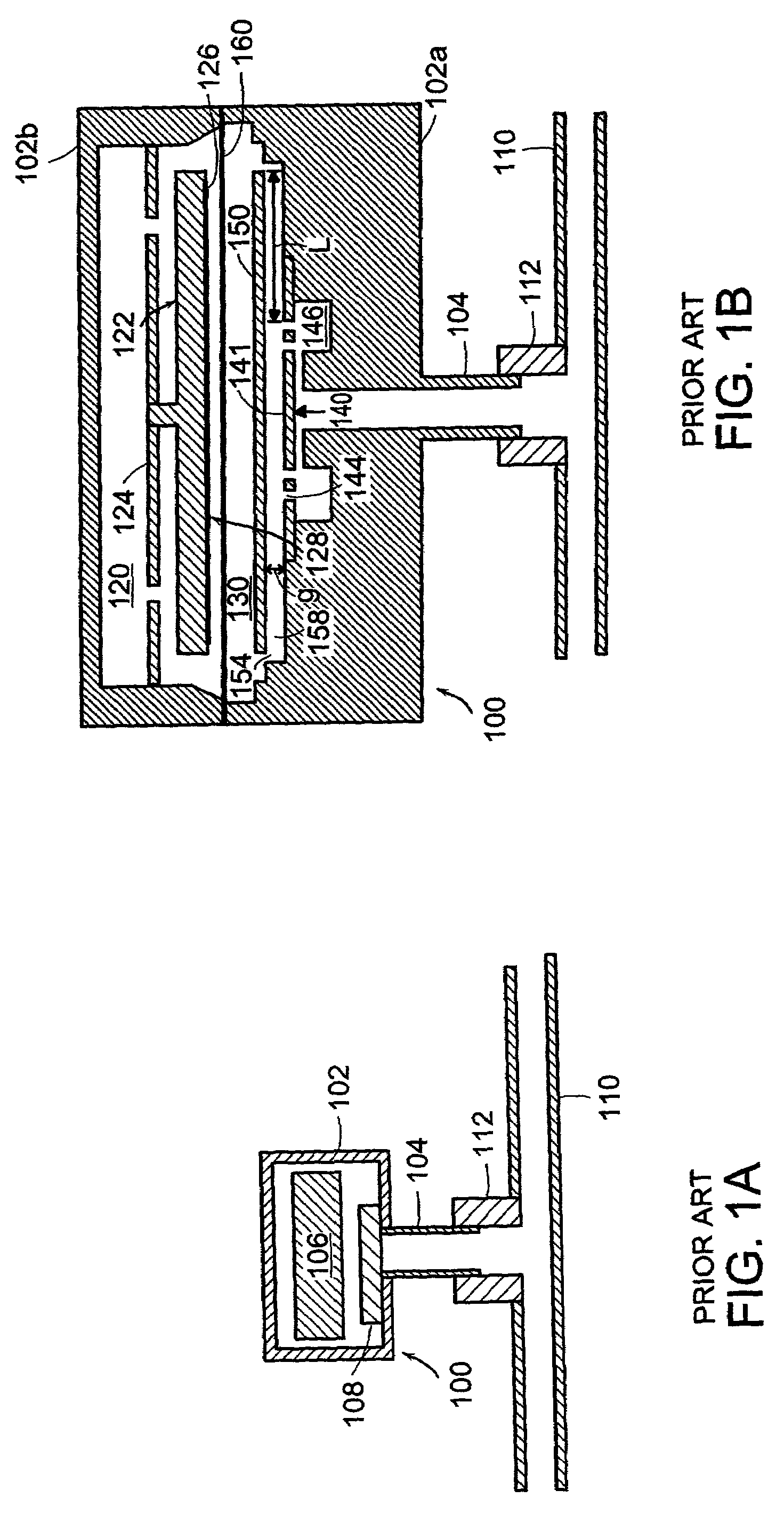
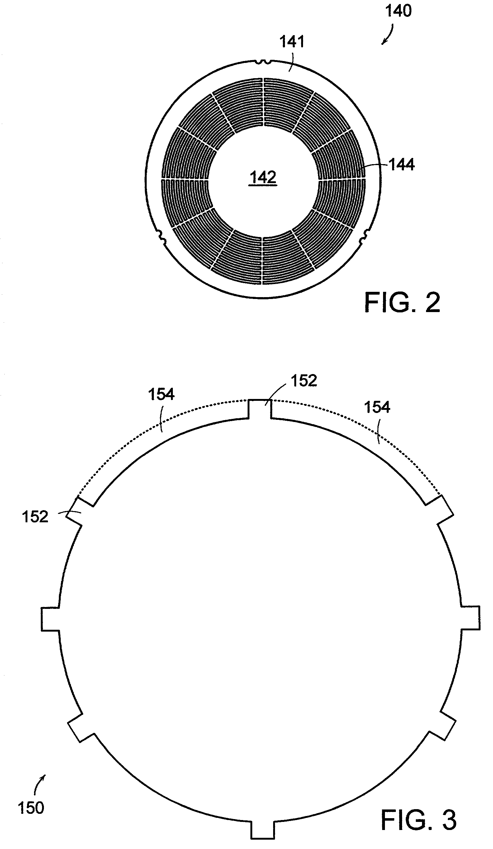
[0030]FIGS. 4A and 4B show a sectional side views of pressure transducers 200 constructed in accordance with the present invention. As shown, in addition to the components associated with prior art transducer 100, transducer 200 additionally includes a deposition trap 280. The deposition trap 280 is disposed in the path between the external source 110 (external source 110 may be for example a gas line or a deposition chamber) and the pressure sensor 106 and may for example be disposed in inlet tube 104, in coupling 112, or partially in both inlet tube 104 and coupling 112. As discussed in greater detail below, material (e.g., gas molecules or particle contaminants) passing through the pathway between the external source 110 and the pressure sensor 106 passes through deposition trap 280 prior to reaching the pressure sensor 106. In embodiments including a diaphragm 160, material passes through deposition trap 280 prior to reaching or contacting the diaphragm 160. As is also discussed...


PUM

PropertyMeasurementUnit
pressureaaaaaaaaaa
aspect ratioaaaaaaaaaa
lengthaaaaaaaaaa

Abstract

The disclosed pressure transducer assembly includes a housing, a pressure sensor disposed within the housing, a coupling establishing a sealed pathway between the housing and an external source of gas or fluid, and a deposition trap disposed in the pathway. The deposition trap provides a plurality of channels, each of the channels being narrower than the pathway.

Description

BACKGROUND OF THE INVENTION[0001]FIG. 1A shows a sectional side view of a prior art capacitive pressure transducer 100. For convenience of illustration, FIG. 1A, as well as other figures in the present disclosure, are not drawn to scale. As shown, transducer 100 includes a housing 102, a capacitive pressure sensor 106 disposed within housing 102, an inlet tube 104, and a filtering mechanism 108. For convenience of illustration, many details of transducer 100 are omitted from FIG. 1A. However, such sensors are well known and are described for example in U.S. Pat. Nos. 5,911,162 and 6,105,436 and U.S. patent application Ser. Nos. 09 / 394,804 and 09 / 637,980.[0002]Briefly, transducer 100 is normally coupled to a gas line, or some other external source of gas or fluid, 110 by a coupling 112. In operation, sensor 106 generates an output signal representative of the pressure within the external source 110.[0003]Pressure transducers such as transducer 100 are often used in integrated circuit...

Claims


Application Information

Patent Timeline
Patent Type & Authority Patents(United States)
IPC IPC(8): G01L9/12G01L19/00G01L19/06
CPCG01L19/0636G01L9/00G01L19/06
Inventor TRAVERSO, ROBERT
Owner MKS INSTR INC
Why Eureka
Try Eureka