Communicating device and method of locking out an item of equipment

a technology of communication device and equipment, which is applied in the direction of identification means, greenhouse gas reduction, instruments, etc., can solve the problems of difficult supervision of these lockouts, inability to guarantee the mechanical locking of an item of equipment, and human error in the installation of lockouts, so as to avoid consuming electrical energy stored and achieve sufficient autonomy

Inactive Publication Date: 2011-08-18
ELECTRICITE DE FRANCE
View PDF8 Cites 11 Cited by
  • Summary
  • Abstract
  • Description
  • Claims
  • Application Information

AI Technical Summary

Benefits of technology

In an advantageous embodiment, the method comprises a step of prior preparation of the device comprising the verification of the last item of charge data transmitted to the supervision system by the communicating device, which makes it possible to verify that the device has sufficient autonomy before associating it with the equipment.
In another advantageous embodiment, the method comprises a step of activation of the communicating device following its association with the item of equipment as well as the verification of the communication between the communicating device and the remote supervision system, in order to avoid consuming the electrical energy stored in the local power supply before being assured that communication with the supervision system is correctly established.

Problems solved by technology

In fact, the installation of lockouts can be subject to human error and, moreover, the supervision of these lockouts is difficult to carry out when the latter involve a multitude of items of equipment situated in places which are difficult to access, as is the case with valves in an industrial installation.
However, these communicating systems are specifically adapted to transportable items of equipment and do not guarantee the mechanical locking of an item of equipment such as a valve.
Moreover, the autonomy of the electrical power supply of the devices described in these communicating systems is not monitored, which makes them unsuitable for an industrial environment in which it is appropriate to limit as much as possible interventions on lockouts which can be installed over a long period.

Method used


Image

  • Communicating device and method of locking out an item of equipment
  • Communicating device and method of locking out an item of equipment
  • Communicating device and method of locking out an item of equipment

Examples


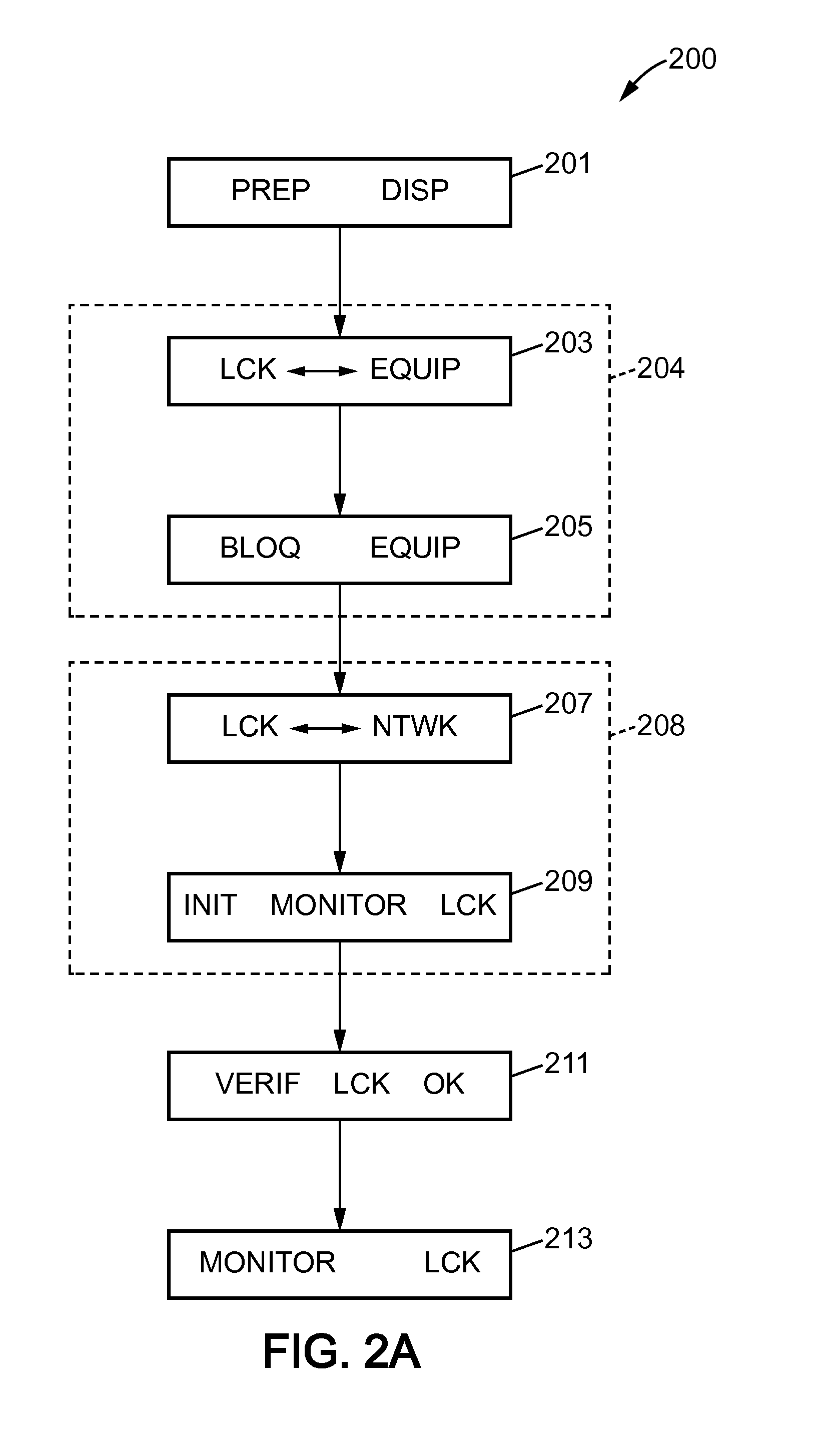
Embodiment Construction

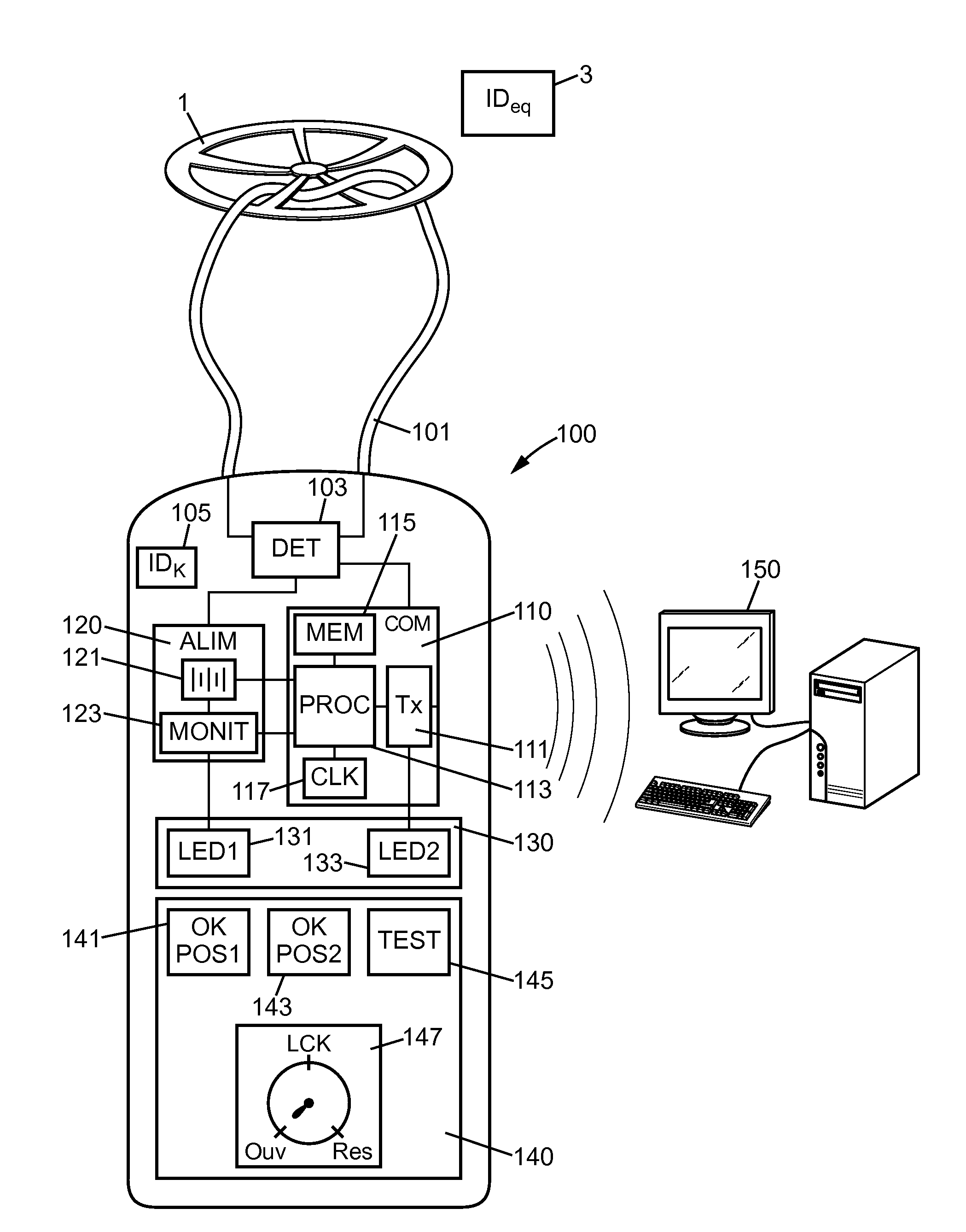
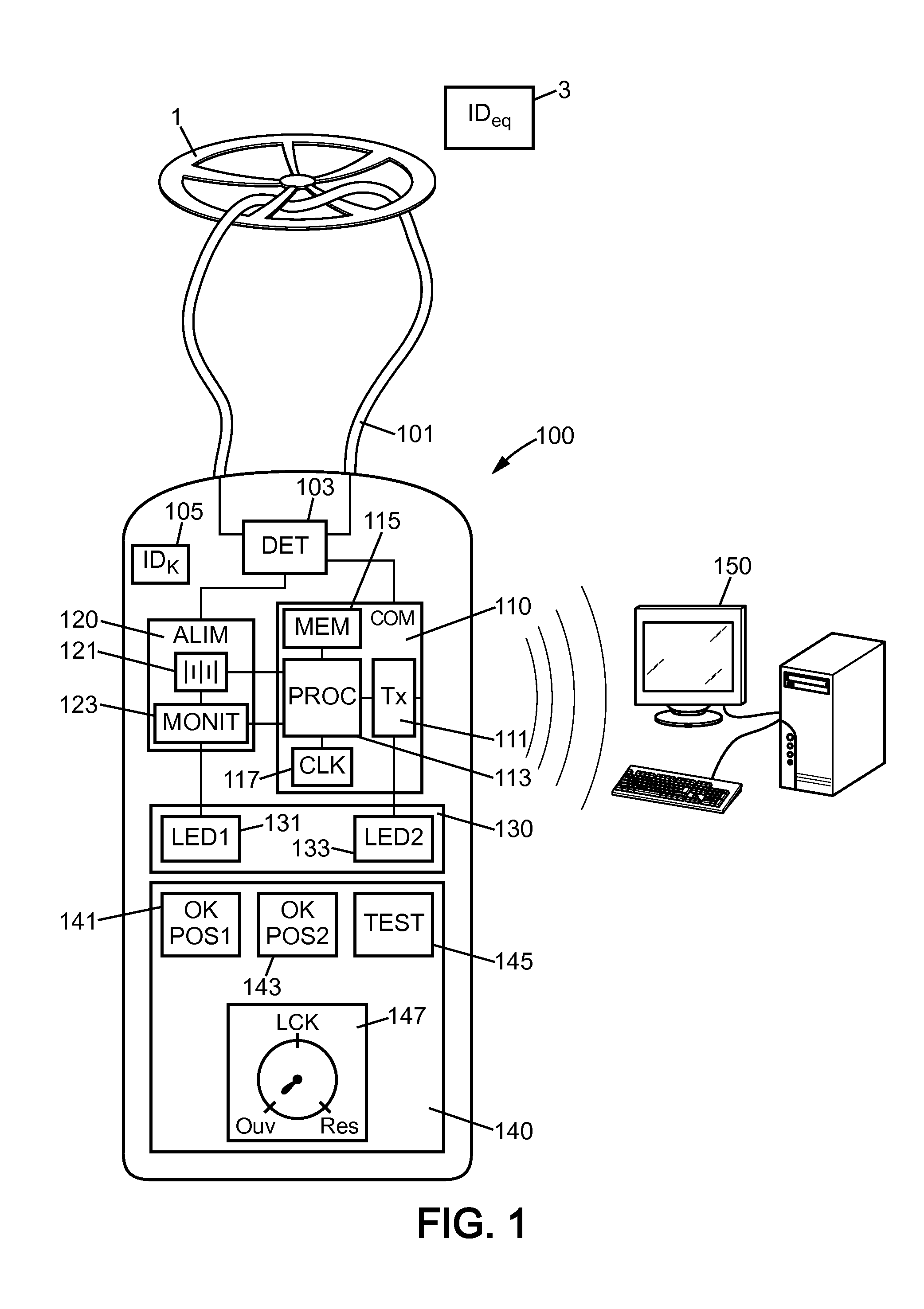
Reference will firstly be made to FIG. 1 in which is shown a communicating lockout device 100 intended to lock out an item of equipment 1 in a fixed position. Such an item of equipment can for example be a valve in an industrial installation, which can be locked out in the open or closed position depending on the context.

For this purpose, the device 100 comprises locking means 101 capable of keeping the item of equipment 1 in a specified fixed position. Such locking means 101 can consist of a cable capable of mechanically tightly holding the item of equipment (the control wheel of a valve by way of purely illustrative example) in order to keep it in a given position.

The device 100 also comprises a communication module 110 capable of communicating data to a supervisor, in particular data relating to the locking means 101 in order to inform the supervisor about the status these means.

Such a communication module 110 thus comprises a transmission unit 111 in order to allow the connectio...


PUM


Abstract

A communicating lockout device of an item of equipment comprising locking means able to maintain the equipment in a fixed position, a communication module able to communicate data relating to said device and a local power supply module adapted to supply electrically at least the communication module, the power supply module comprising a charge monitoring unit arranged for measuring the charge level of the local power supply module. The invention also relates to a network for the supervision of a plurality of items of equipment using such a communicating device as well as to a corresponding supervision method.

Description

CROSS-REFERENCE TO RELATED PATENT APPLICATIONThis application claims the benefit of French Patent Application No. 10 50217, filed on Jan. 14, 2010, in the French Institute of Industrial Property, the entire contents of which is incorporated herein by reference.FIELD OF THE INVENTIONThe invention relates to the field of the supervision of items of equipment in industrial installations, and more particularly the use of communicating devices making it possible to lock out certain items of equipment in such industrial is installations.BACKGROUNDIn large scale industrial installations, and in particular in the nuclear industry, padlocks and chains are currently used for mechanically locking an item of equipment, in general a valve, in a position required by the operation. Such mechanical locking in a fixed position is required either for personnel safety constraints, or for nuclear safety constraints. This type of mechanical locking is commonly called “lockout” or “immobilization”.The st...

Claims


Application Information

Patent Timeline
Patent Type & Authority Applications(United States)
IPC IPC(8): G08B29/00G08B21/00
CPCG09F3/0329E05B45/005Y02E30/30G05B23/00G21C17/00
Inventor DIONIS, FRANCOISPERRIER DE LA BATHIE, ERICJOLY, VINCENT
Owner ELECTRICITE DE FRANCE
Why Eureka
Try Eureka