Aircraft provided with aerodynamic seal for reduction of noise generated by aircraft control surfaces

a technology of aircraft control surface and aerodynamic seal, which is applied in the direction of aircraft control, influencers by generating vortices, aircraft components, etc., to achieve the effects of low installation effort, low cost and light weigh

Active Publication Date: 2014-02-25
YABORA IND AERONAUTICA SA
View PDF10 Cites 13 Cited by
  • Summary
  • Abstract
  • Description
  • Claims
  • Application Information

AI Technical Summary

Benefits of technology

[0020]According with the mentioned above, it is clear that the development of a solution for the aerodynamic generated noise from the trailing edge flaps that conciliates the requirements of low cost, easy retrofit on operating aircrafts, low weight and little or no influence on drag / lift has been a challenge confronting engineers during the last decades.
[0030]In view of the above, in order to be effective as a noise control measure, any solution to be applied on the trailing edge flaps must act towards weakening the vortex subsystems generated at the lower and / or upper flap side edge contour, aiming to avoid any merging between them. In addition, since the merge process is avoided, the monopole, dipole and quadrupole acoustic sources represented by the jet-like flow in the vortex core, by the vortex pressure fluctuations acting with the flap upper surface and by the oscillating and rotating instabilities within the vorticity field respectively are substantially reduced, the resulting radiated noise decreases as well.
[0032]It is proposed a new project for reduction of the aerodynamic noise generated by the wing and control surfaces of an aircraft. This goal is reached through an aerodynamic seal to be installed between the fixed parts of the aircraft and its control surfaces, having a larger width than the space among the surfaces and with perforations covering its extension. These perforations will generate small vortexes that will weaken the main vortex generated in these extremities (edges), without any aerodynamic disadvantage when the aircraft is in the cruise configuration. Further, this project can be installed easily in already existent aircrafts, once it just requests the change of the common aerodynamic seals that are already installed on the aircraft.
[0033]Therefore, for reduction of the noise generated by the edges of the side contours of the flap during the approach phase and landing of commercial airplanes flightz, and also for accomplishment of characteristics of low cost, weight, and easy installation, the perforated sheet seal applied in an extended way on the pressure side of a high flap flap of the invention is a new solution for the problem.
[0034]With the extended width, the lower vortex subsystem that is generated at the lower sharp edge of the flap is prevented of moving upwards. As a consequence, the merging process with the upper vortex subsystem is substantially reduced. Since the merged process is avoided or made more difficult, the amount of noise radiated into the far field is also substantially reduced. The perforations along the blade seal length have the purpose to work as a vortex generator, creating a great number of relatively small individual vortices, avoiding the feed of the main merged vortex with the energy that usually come from the vortices generated at the lower flap sharp edge. The reduction of the strength of the main merged vortex does not reduce the aerodynamic effect of the control surface (lift generated by flaps). In addition the perforations reduce the seal stiffness at certain positions inducing a back and forth movement when it is exposed to the flow, also contributing for the vortex generator performance.
[0037]An important advantage of this invention is that it is relatively inexpensive and simple in construction, with a relatively low installation effort for aircraft that are already in operation (retrofit). Moreover, the solution is rather light in weight and do not cause any significant prejudicial effect on the performance of the control surface.

Problems solved by technology

According with the mentioned above, it is clear that the development of a solution for the aerodynamic generated noise from the trailing edge flaps that conciliates the requirements of low cost, easy retrofit on operating aircrafts, low weight and little or no influence on drag / lift has been a challenge confronting engineers during the last decades.

Method used


Image

  • Aircraft provided with aerodynamic seal for reduction of noise generated by aircraft control surfaces
  • Aircraft provided with aerodynamic seal for reduction of noise generated by aircraft control surfaces
  • Aircraft provided with aerodynamic seal for reduction of noise generated by aircraft control surfaces

Examples


Embodiment Construction

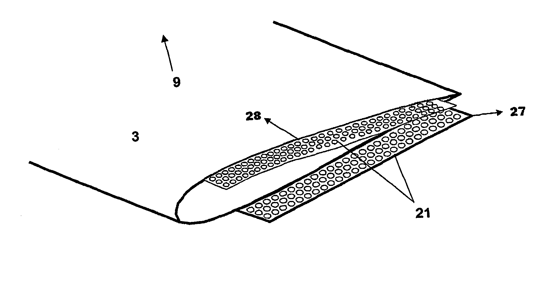
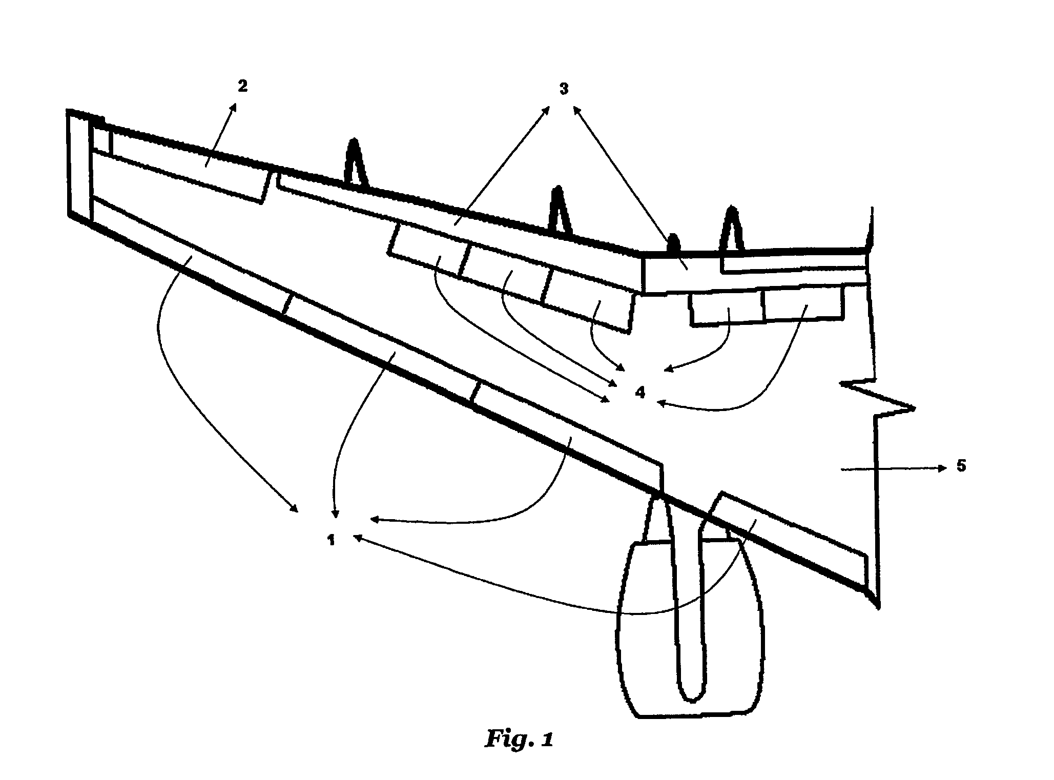
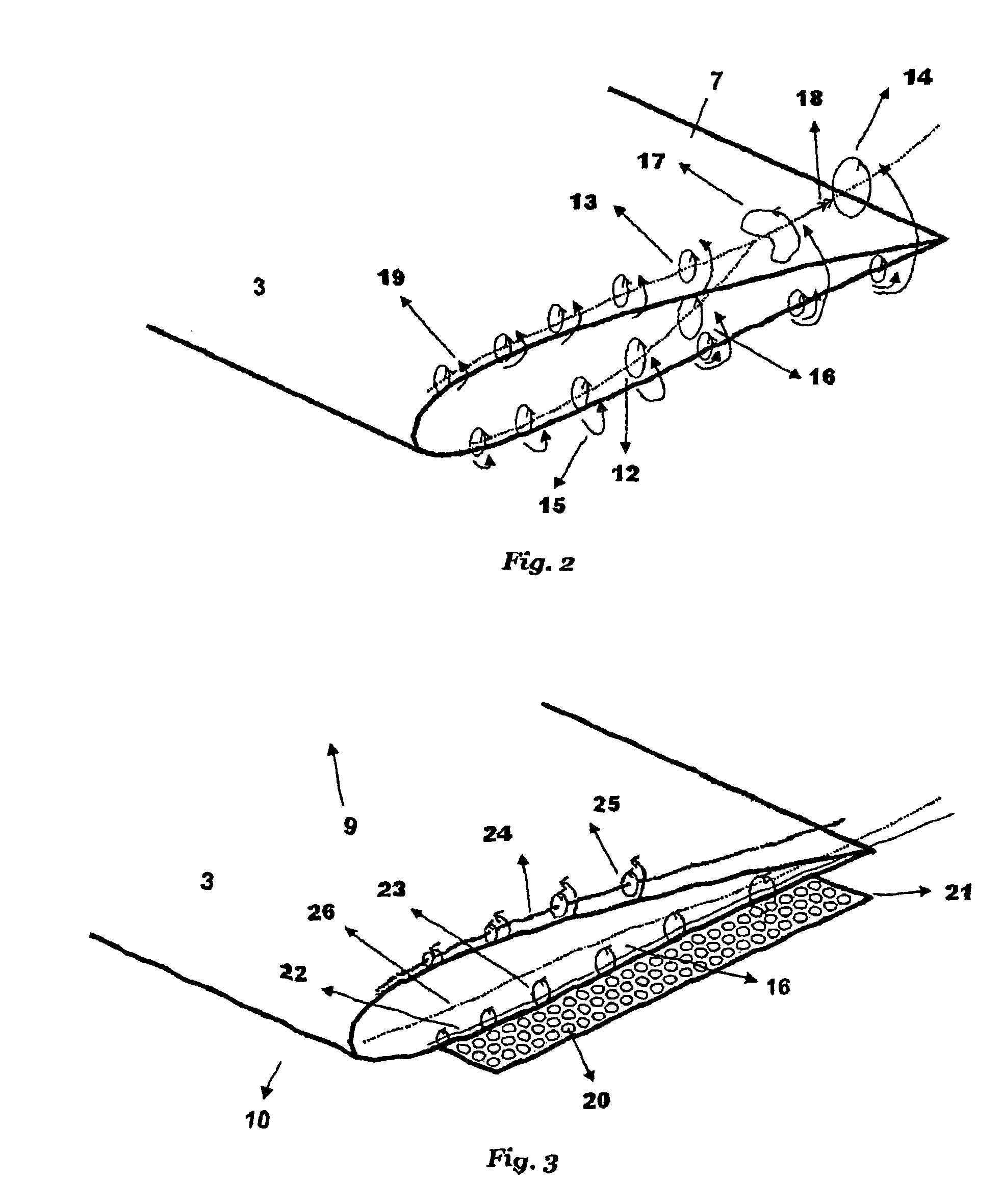
[0044]FIG. 1 shows an aircraft which includes a main element 5 (wing) and a high lift system composed by elements 1 and 3. In the example represented herein, the high lift system comprises a plurality of movable components, such as a trailing edge assembly formed of a plurality of adjacent flaps 3 and a leading edge assembly 1 formed of a plurality of slats. Spoilers 4 and an aileron 2 are also seen in this figure.

[0045]The reduction of the aerodynamic generated noise becomes significant only during the approach and landing phase of flight of an aircraft. During take-off procedures, the engines are set at full power and the noise generated by the high lift devices is completely masked. Moreover, for the majority of take-off procedures both slats and flaps are partially extended and are retracted shortly after lift-off in order to improve the lift-over-drag ratio of the climbout configuration. On the other hand, during landing, both slats 1 and flaps 3 are fully extended. In addition...


PUM


Abstract

Aircraft are provided with a perforated blade seal at the lower and / or upper side edges of a control surface contour, such as a flap, with the purpose of acting as a vortex generator, thereby making it difficult for the lower vortex system to move upwards and merge with the upper vortex system. The perforated blade seals are preferably arranged on the inboard and outboard edges of high lift flaps.

Description

[0001]This application is the U.S. national phase of International Application No. PCT / BR2008 / 000087 filed 27 Mar. 2008, which designated the U.S. and claims priority to Brazil Application No. PI 070143-4 filed 13 Apr. 2007, the entire contents of each of which are hereby incorporated by reference.[0002]The present invention relates to suppression of noise aerodynamically generated by an aircraft, more specifically to the noise generated by control surfaces of aircraft such as flaps, slats, ailerons and spoilers. More particularly this invention relates to a seal for reduction of the aerodynamic noise generated by high lift flap side edges.STATE OF ART[0003]The technological progresses are greatly accompanied by a certain apprehension degree related to the environmental impacts caused by their application. The continuous evolution of transportation means is a clear example of the comfort generated by the possibility of a fast travel movement of the human being, but on the other hand...

Claims


Application Information

Patent Timeline
Patent Type & Authority Patents(United States)
IPC IPC(8): B64C23/00
CPCB64C9/02B64C7/00B64C9/18
Inventor TRICH S, JR., MARIOVALLE DO CARMO, MICAEL GIANINICALDEIRA DA SILVA, BRUNO ARANTESFRANCA BARBOZA, MARCUS VINICIUSLOSADA GOUVEIA, VINICIUS
Owner YABORA IND AERONAUTICA SA
Why Eureka
Try Eureka