Supercharge Your Innovation With Domain-Expert AI Agents!

Distributed energy source system

a distributed energy source and energy source technology, applied in transmission systems, wind energy generation, dc source parallel operation, etc., can solve the problems of large waste of energy, large cost to end users, and inability to provide clean energy, and achieve the effect of facilitating efficient energy usag

Inactive Publication Date: 2017-01-31
WISE POWER INC
View PDF27 Cites 0 Cited by
  • Summary
  • Abstract
  • Description
  • Claims
  • Application Information

AI Technical Summary

Benefits of technology

Enables efficient energy usage and management by directing energy flow based on real-time data, allowing excess energy to be stored or returned to the grid, improving grid performance and reducing waste, and providing strategic placement of energy sources to address peak demand issues.

Problems solved by technology

. . supreme engineering achievement of the 20th century.” Unfortunately, the power grid is quickly aging such that outages and inefficiencies result in great costs to end users.
A growing movement to provide clean energy, utilizing such sources as wind, currently suffers from significant inefficiencies due to limitations within the power grid.
Commercial wind farms often produce much greater energy than is realized, but the transmissions lines cannot accommodate the amount of energy produced, thereby resulting in large amounts of wasted effort.
Residential applications are often seen as impractical due to costs, lack of providing enough energy during peak demand, and wasted energy during off-peak times. In addition, there is no application that provides two-way communication between end users and the distribution source.
Current efforts to develop a Smart Grid are ongoing, but these efforts are generally limited to increasing reliability, efficiency, and safety of the power grid, largely in an effort to reduce threats of tenor attacks, resulting in large scale power outages.
Unfortunately, there is no system that currently provides the end user the ability to utilize and manage distributed energy sources.
Further, there is no system that currently provides the capability of the distributed energy sources, such as in residential applications, to return unused energy to the power grid, or store excess energy for later use by the end-user.
Still further, there is no system that provides the end user, or other interested party, such as a stakeholder, the ability to collect usage and generation data, to deliver electricity more efficiently and detect problems within the system, and provide information that allows for strategic placement of distributed generation sources for overall performance improvement.

Method used


Image

  • Distributed energy source system
  • Distributed energy source system
  • Distributed energy source system

Examples


Embodiment Construction

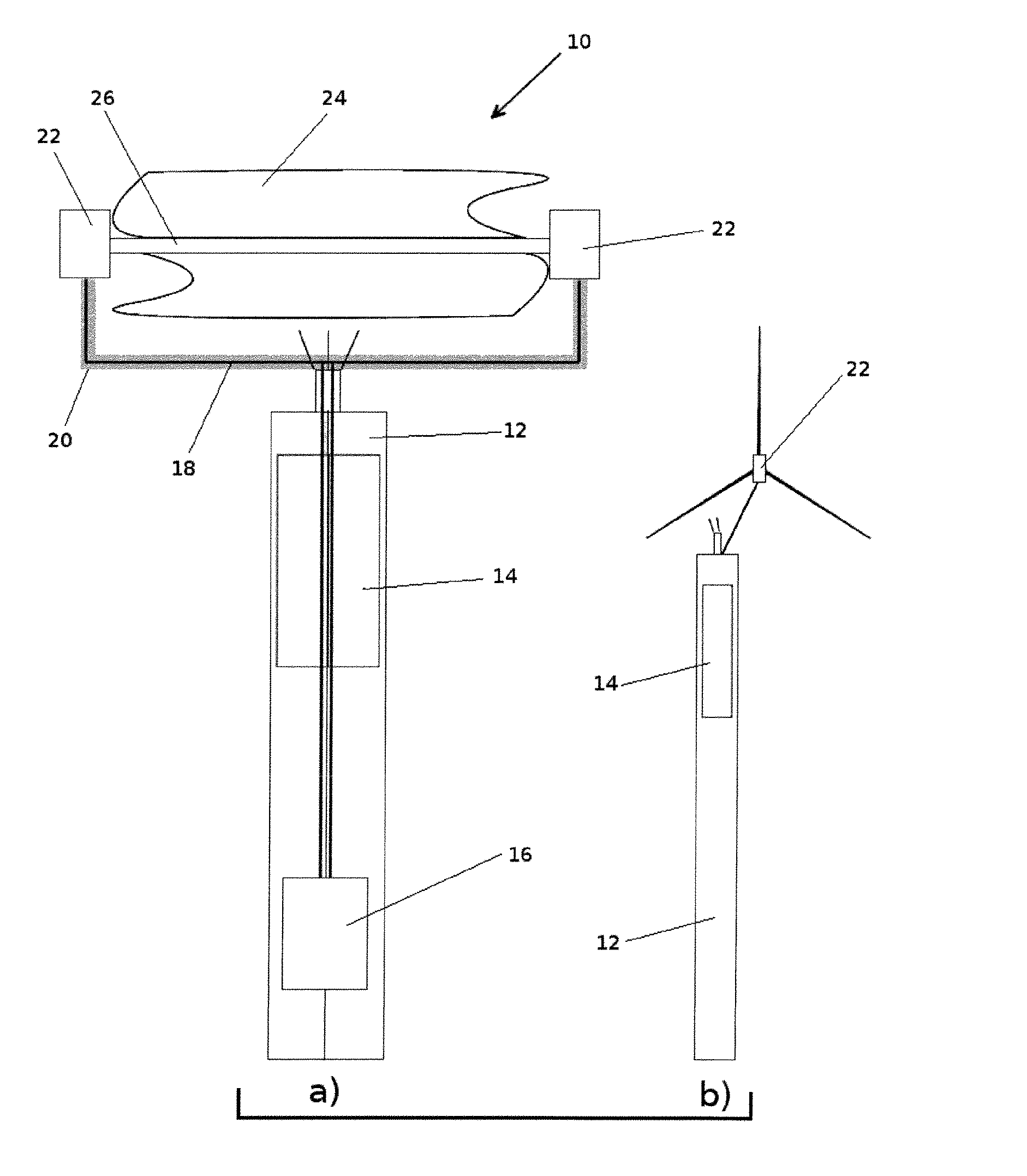
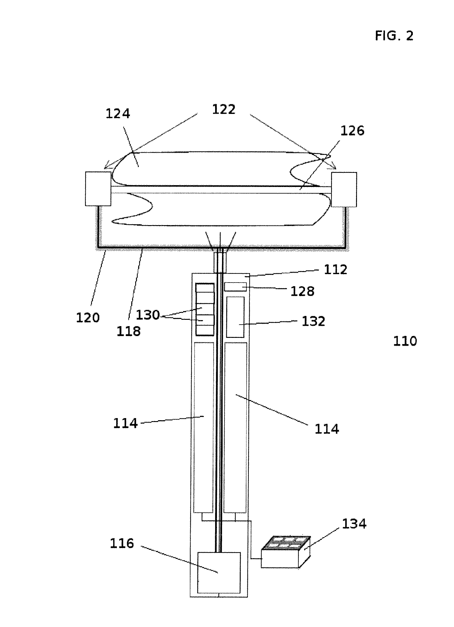
[0020]The present invention solves the above-described problems and provides a distinct advance in the art of renewable energy sources. More particularly, the present invention provides a system that interacts with and provides two-way communication and energy flow between distributed energy sources, end-users, and utilities. The present invention can be placed near the consumer to generate electric power directly to end-users and to provide excess power back to the distribution system.

[0021]In one embodiment, the present invention comprises a computer program stored on a computer-readable media for directing operation of a computer, at least one distributed energy source, an energy storage device, and an electronic network. The computer program communicates across the electronic network with consumer's appliances, the end-user, and the energy distribution source and provides a near real-time graphical representation of the status of the various system components, including energy-r...


PUM


Abstract

An energy management system includes at least one distributed energy source for producing energy, the distributed energy source in electrical communication with at least one consumer device to be powered by electric power, and in electrical communication with an electric utility. The device also includes a CPU in communication with the at least one distributed energy source, the CPU operable to control the flow of energy produced by the at least one distributed energy source. The CPU manipulates the flow of energy to provide efficient usage of the energy based on information from the at least one consumer and the electric utility.

Description

CROSS-REFERENCE TO RELATED APPLICATIONS[0001]The present invention claims priority of U.S. Provisional Patent Application No. 61 / 289,244, filed on Dec. 22, 2009, and entitled “Distributed Energy Source System,” which is incorporated herein by reference in its entirety.FIELD OF THE INVENTION[0002]The present invention relates generally to renewable energy sources. More particularly, the present invention concerns combinations of various electric power generation techniques and processes into a single delivery device that is operable for two-way communication with the Smart Grid.BACKGROUND OF THE INVENTION[0003]The North American power grid was once called the “ . . . supreme engineering achievement of the 20th century.” Unfortunately, the power grid is quickly aging such that outages and inefficiencies result in great costs to end users.[0004]A growing movement to provide clean energy, utilizing such sources as wind, currently suffers from significant inefficiencies due to limitation...

Claims


Application Information

Patent Timeline
Patent Type & Authority Patents(United States)
IPC IPC(8): H02J1/12H02J3/38
CPCH02J3/386Y02E10/763Y10T307/359H02J2300/28H02J3/381Y02E10/76
Inventor WILLIAMS, KEVIN JAMES
Owner WISE POWER INC
Features
  • R&D
  • Intellectual Property
  • Life Sciences
  • Materials
  • Tech Scout
  • Unparalleled Data Quality
  • Higher Quality Content
  • 60% Fewer Hallucinations
Learn More