
Artificial structure for attracting fish

a technology of artificial structure and fish, which is applied in the field of artificial structure, can solve the problems of destroying many of these habitats, further affecting other organisms in the food chain, and affecting local business cycles as well

Active Publication Date: 2017-02-07
KING DAVID +1
View PDF12 Cites 6 Cited by
  • Summary
  • Abstract
  • Description
  • Claims
  • Application Information

AI Technical Summary

Benefits of technology

The invention is an artificial structure designed to attract fish in icy environments. It consists of a central mast with pivoting shafts that can be extended into water. The structure creates an artificial shelter or shield for fish, providing motivation for them to stay within the area. The shafts are angled, allowing fish to rest and stay for a longer period of time. This invention can also be used for fishermen to attract fish in areas where they tend to congregate. It provides a convenient and selective device for icy fishing. Additionally, it provides a greater surface area of habitats for fish to rest and hang around.

Problems solved by technology

However, many of these habitats have been destroyed by natural phenomena such as hurricanes, floods, and the like.
This loss of habitats has led to entire species being lost from certain bodies of waters, thus further affecting other organisms in the food chain.
Even fishermen, who at one time would frequent certain fishing spots, would stop their visits, thus affecting local business cycles as well.
Certain serious drawbacks have resulted for example, in using artificial or natural tree limbs as fishing lines often become enwrapped with the limbs and have to be cut free.
Other specific devices which have been used are difficult to retrieve or move as may be desired from time to time or from location to location.
Also, artificial devices can be expensive, easily damaged and are therefore little used.
Other artificial devices have provided an area that attracts fish momentarily, but does not encourage the fish to stay within the area for a length of time since the fish must remain active.
In icy environments, government restrictions prevent fishermen from deploying permanent or semi-permanent structures.
The prior art fails to show a device that can be deployed within the confines of an ice fishing hole and subsequently removed.
The prior art patents are very limited in their teaching and utilization, and an improved artificial structure for attracting fish in an icy environment is needed to overcome these limitations.

Method used


Image

  • Artificial structure for attracting fish
  • Artificial structure for attracting fish
  • Artificial structure for attracting fish

Examples


Embodiment Construction

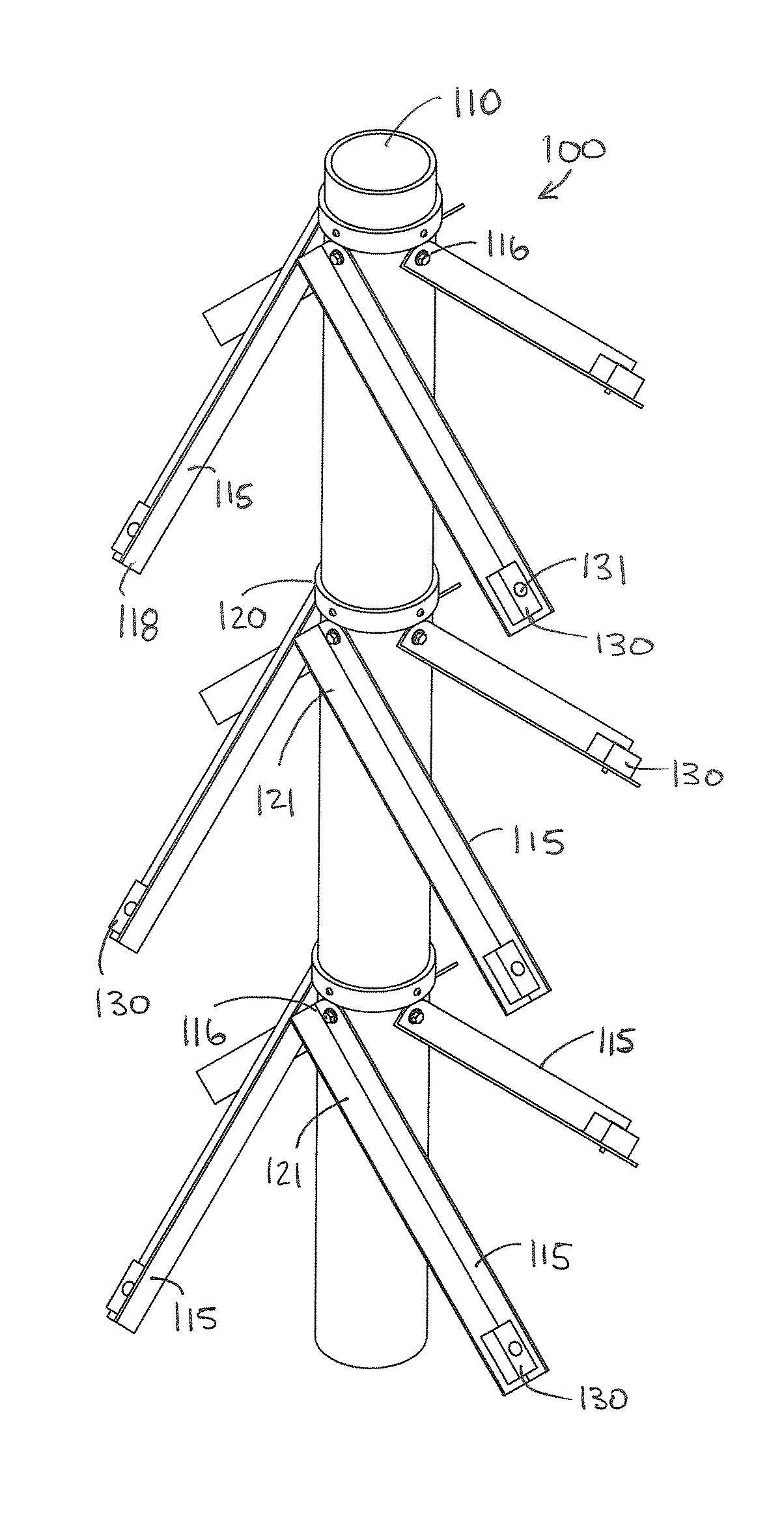
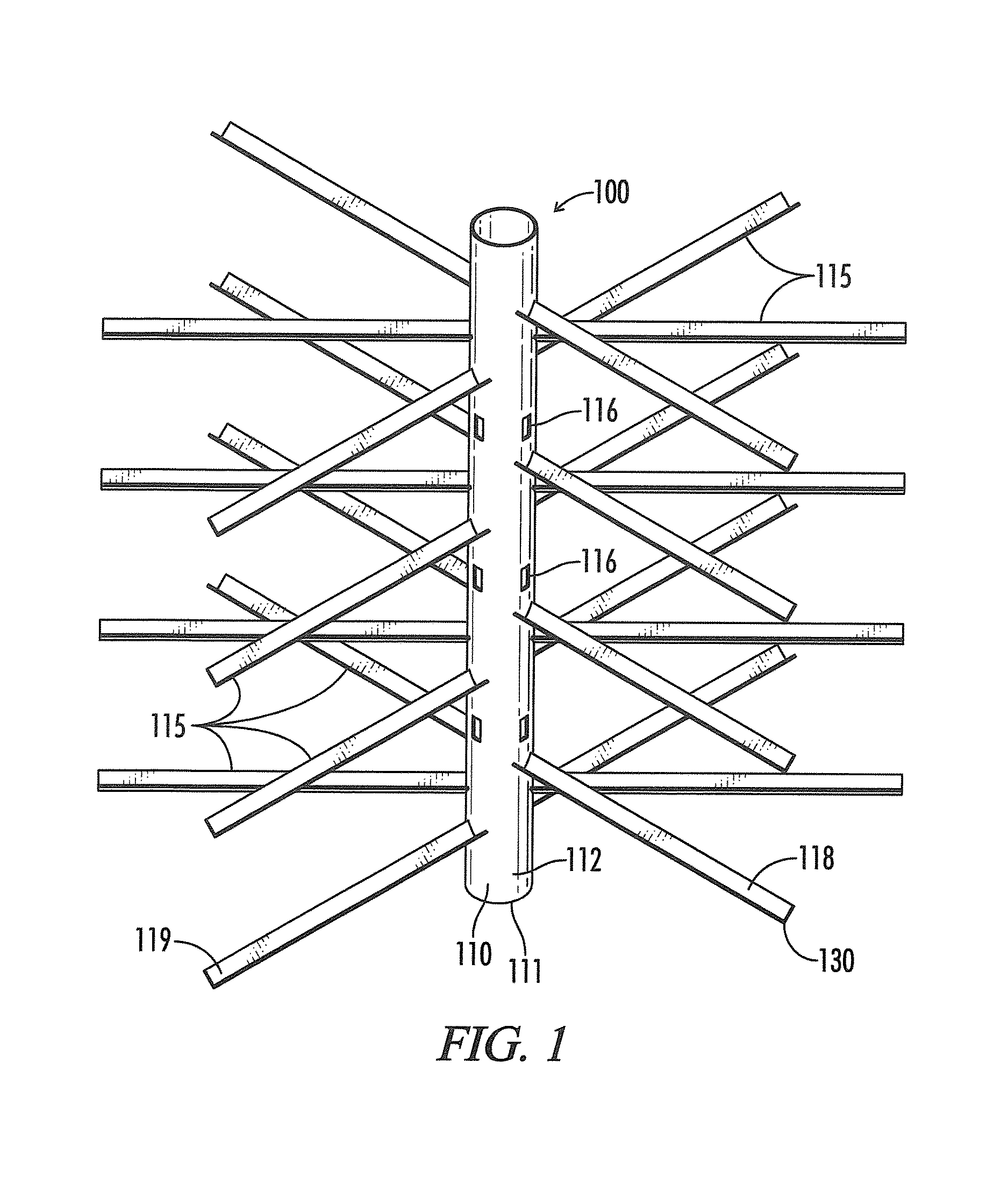
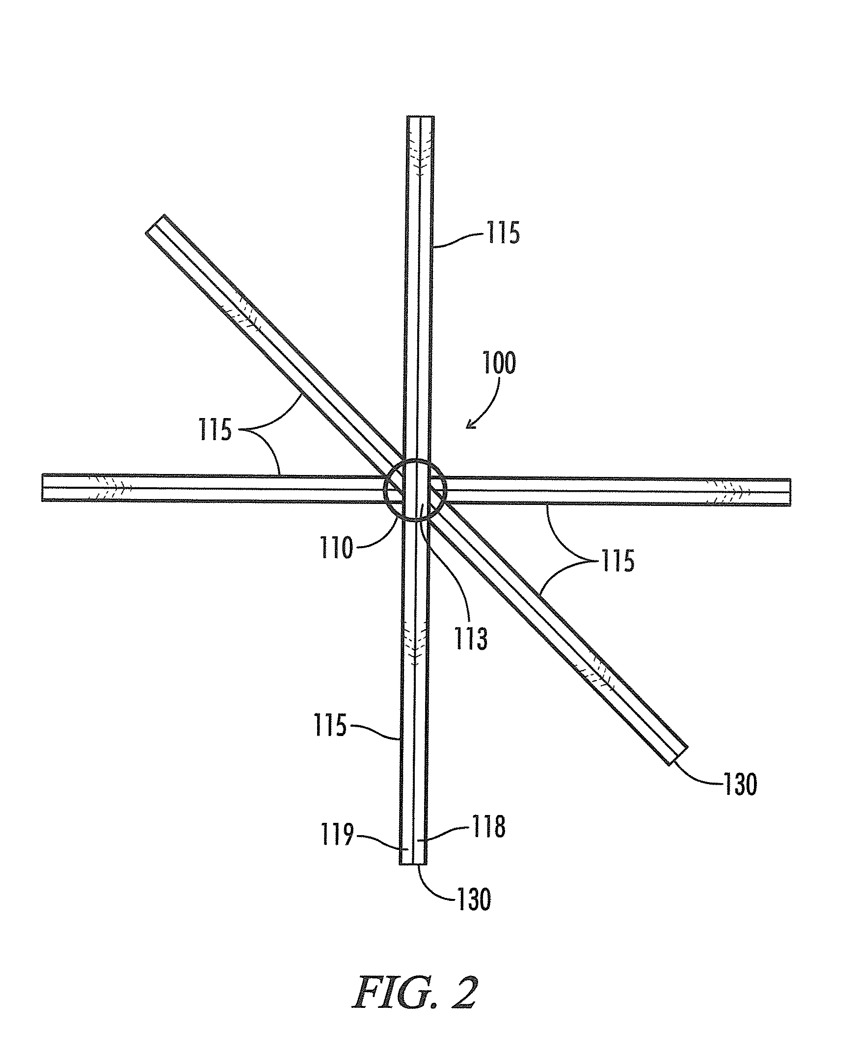
[0047]The present invention is an artificial structure 100 for attracting fish. The structure 100 is comprised of central mast 110 with a series of outward extending shafts 115. The structure 100 is composed of material, such as a PVC material, suitable for lowering to the bottom of a lake, stream, pond or other similar body of water. A cable may also be provided for attaching to a dock to suspend the structure 100 or attach weight. Additionally, a docking platform may be utilized to secure multiple structures (100) (not shown) at a single location. The structure 100 forms an artificial habitat or shield for any fish who may be seeking refuge from predators or seeking other fish or food to eat.

[0048]The central mast 110 as shown in the drawings is an elongated, cylindrical tube with open ends, but it is envisioned that the mast 110 can be a variety of shapes. Along the length of the mast 110 are a variety of shaft apertures 114 spaced equidistant around the circumference of the mast...


PUM


Abstract

A structure for attracting fish in lakes and ponds is presented that includes a central mast with one or more angled shafts for the fish to rest upon and congregate near.

Description

CROSS-REFERENCE TO RELATED APPLICATIONS[0001]This application claims priority to and is a continuation-in-part of U.S. application Ser. No. 13 / 600,639, filed Aug. 31, 2012 and claims priority to and is a continuation-in-part of U.S. application Ser. No. 13 / 591,648, filed Aug. 22, 2012, which claims priority to and is a continuation-in-part of U.S. application Ser. No. 12 / 807,230, filed Aug. 21, 2010, which claims priority to and is a continuation-in-part of U.S. Application Ser. No. 61 / 337,770, filed Feb. 10, 2010, which are both hereby incorporated by reference in their entirety.STATEMENT REGARDING FEDERALLY SPONSORED RESEARCH OR DEVELOPMENT[0002]Not Applicable.REFERENCE TO A MICROFICHE APPENDIX[0003]Not Applicable.BACKGROUND OF THE INVENTION[0004]1. Field of the Invention[0005]The present invention pertains to artificial structures adapted for submersion in bodies of water. The artificial structure is configured to be attractive to fish, and thus to create an artificial habitat ar...

Claims


Application Information

Patent Timeline
IPC IPC(8): A01K61/00A01K97/01
CPCA01K61/006A01K97/01A01K61/73A01K61/78Y02A40/81
Inventor KING, DAVIDSTEWART, RAY
Owner KING DAVID
Learn More