Liquid ejecting apparatus
a technology of liquid ejecting apparatus and ejector, which is applied in the direction of printing, etc., can solve the problems of degrading an image, degrading the landing position of a main droplet ejecting from an ejector, and the influence of airflow on the ejector, so as to achieve efficient removal of mist
- Summary
- Abstract
- Description
- Claims
- Application Information
AI Technical Summary
Benefits of technology
Problems solved by technology
Method used
Image

Examples
first embodiment
[0030]An embodiment according to the present invention will be described in detail with reference to the attached drawings.
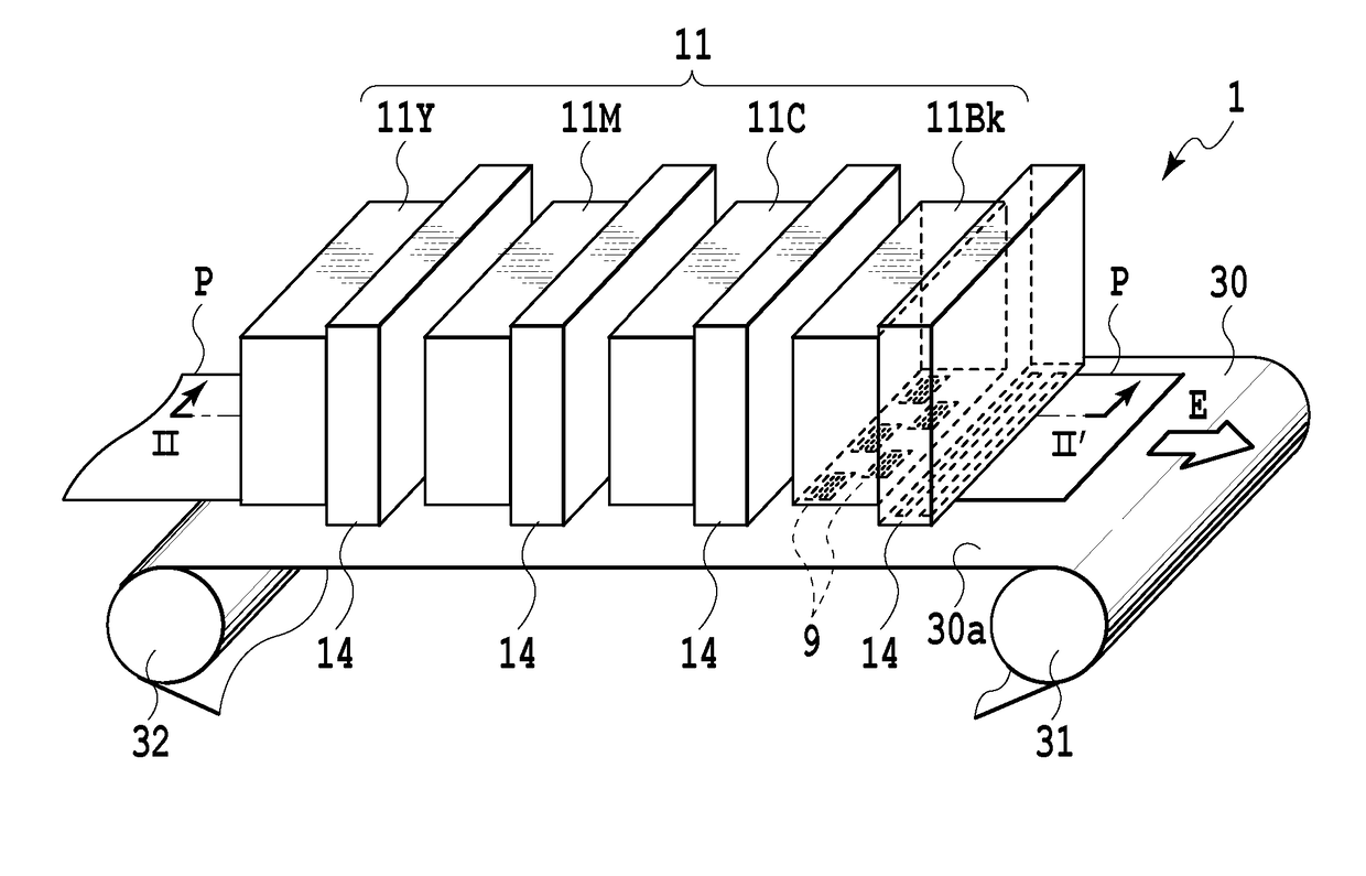
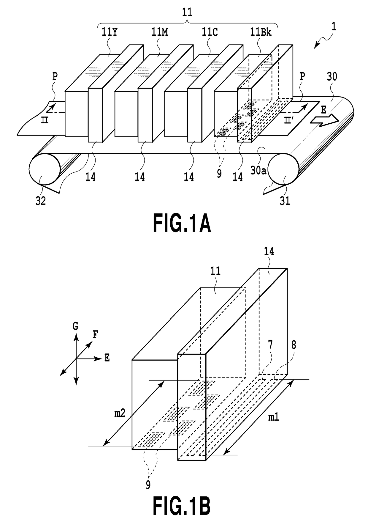
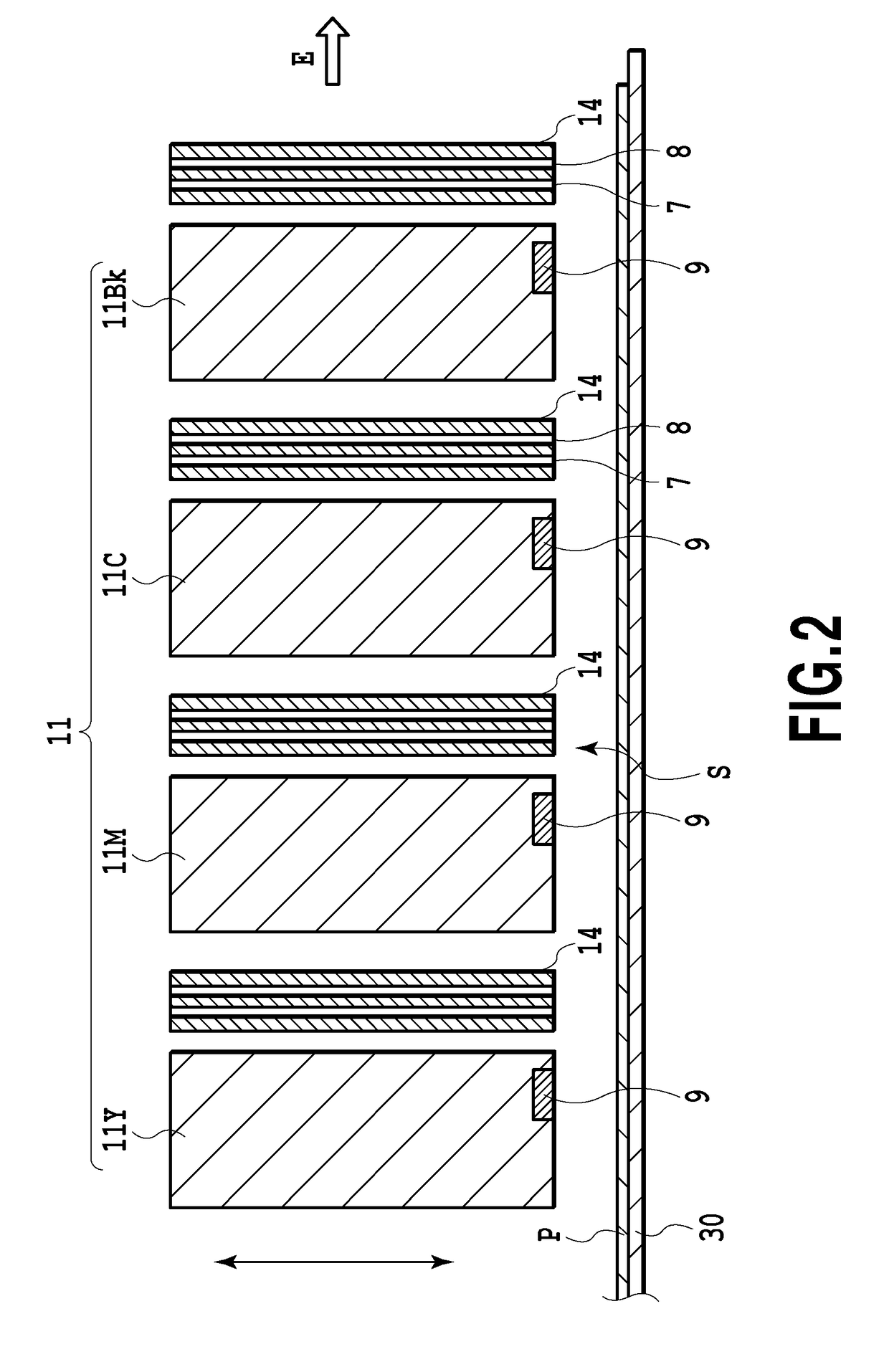
[0031]FIG. 1A is a perspective view schematically showing the configurations of essential parts of a liquid ejecting apparatus that is applied to an embodiment according to the present invention; FIG. 1B is a perspective view showing the configuration and arrangement of a liquid ejecting unit (i.e., a print head) and a mist removing head shown in FIG. 1A; and FIG. 2 is a vertical side view schematically showing the arrangement of the print head and the mist removing head shown in FIG. 1A, taken along a line II-II′.
[0032]In FIG. 1A, FIG. 1B, and FIG. 2, a liquid ejecting apparatus 1 in the present embodiment is a full-line type ink jet printing apparatus in which a plurality of elongated print heads 11Y, 11M, 11C, and 11Bk extending in a planar direction (i.e., a direction F) perpendicular to a movement direction (i.e., a direction E) of a print medium P are arra...
second embodiment
[0059]Next, a description will be given of a second embodiment according to the present invention. In the first embodiment, an angle θ1 defined by a direction d1 of the airflow in the suction hole 7 at the mist removing head and a head surface 14a and an angle θ2 defined by a direction d2 of the airflow in the blowing hole 8 and the head surface 14a are equal to each other (90 degrees), as shown in FIG. 7A. In contrast, in the second embodiment, the angle θ1 defined by the head surface 14a and the direction d1 of the airflow in the suction hole 7 and the angle θ2 defined by the head surface 14a and the direction d2 of the airflow in the blowing hole 8 are different from each other, as shown in FIGS. 7B to 7D.
[0060]As shown in FIGS. 7B to 7D, the suction hole 7 and the blowing hole 8 in the mist removing head 14 can be formed at various angles in various directions with respect to the head surface 14a. Moreover, it is unnecessary that the airflow rate at the suction hole 7 is equal t...
third embodiment
[0061]Subsequently, a description will be given of a third embodiment according to the present invention with reference to FIGS. 8A and 8B. FIG. 8A is a bottom view schematically showing the configuration of the print head in the present embodiment; and FIG. 8B is a cross-sectional view taken along a line VIIIB-VIIIB′ of FIG. 8A. The above-described first and second embodiments are configured such that the plurality of print heads (11Y, 11C, 11M, and 11Bk) are disposed, and furthermore, the mist removing heads 14, each having the suction hole 7 and the blowing hole 8, are disposed independently of the print heads 11 downstream of each of the plurality of print heads. In contrast, in the third embodiment, a plurality of ejection port arrays 105A for ejecting different color inks are formed inside of a single print head 11, as shown in FIG. 8A. A blowing hole 8 and a suction hole 7 are formed in parallel downstream of each of the ejection port arrays 105A.
[0062]Moreover, as shown in F...
PUM
 Abstract
Description
Claims
Application Information
 - R&D
- Intellectual Property
- Life Sciences
- Materials
- Tech Scout
- Unparalleled Data Quality
- Higher Quality Content
- 60% Fewer Hallucinations
Browse by: Latest US Patents, China's latest patents, Technical Efficacy Thesaurus, Application Domain, Technology Topic, Popular Technical Reports.
© 2025 PatSnap. All rights reserved.Legal|Privacy policy|Modern Slavery Act Transparency Statement|Sitemap|About US| Contact US: help@patsnap.com