Sleeve for a sawing bead obtained by metal injection moulding

a technology of metal injection moulding and sawing bead, which is applied in the direction of metal sawing equipment, metal sawing tool making, manufacturing tools, etc., can solve the problems of premature failure of the cord and wear of the steel cord, and achieve the effect of avoiding blemishes and easy operation

Inactive Publication Date: 2017-11-28
NV BEKAERT SA
View PDF17 Cites 2 Cited by
  • Summary
  • Abstract
  • Description
  • Claims
  • Application Information

AI Technical Summary

Benefits of technology

[0010]The primary object of the invention is to provide a sleeve that is cheaper to manufacture in big quantities. A further object is to provide a sleeve that is specifically adapted for attaching an abrasive layer on it by laser cladding. Another objective is to offer a method that enables to make the metal sleeves with a large degree of freedom in terms of shape and material composition. The final object of the invention is to provide a sawing bead and a sawing cord comprising sawing beads that have particular advantages to currently known sawing cords by virtue of their metal sleeves.

Problems solved by technology

As the sleeve is close to the steel cord or even in contact therewith there is the risk for wear of the steel cord.
Indeed as the sleeve is relatively rigid compared to the flexible cord the cord may contact the rim of the sleeve upon bending leading to premature failure of the cord.
This is expensive, certainly when one wants to have a controlled and more complicated shape.

Method used


Image

  • Sleeve for a sawing bead obtained by metal injection moulding
  • Sleeve for a sawing bead obtained by metal injection moulding
  • Sleeve for a sawing bead obtained by metal injection moulding

Examples


Embodiment Construction

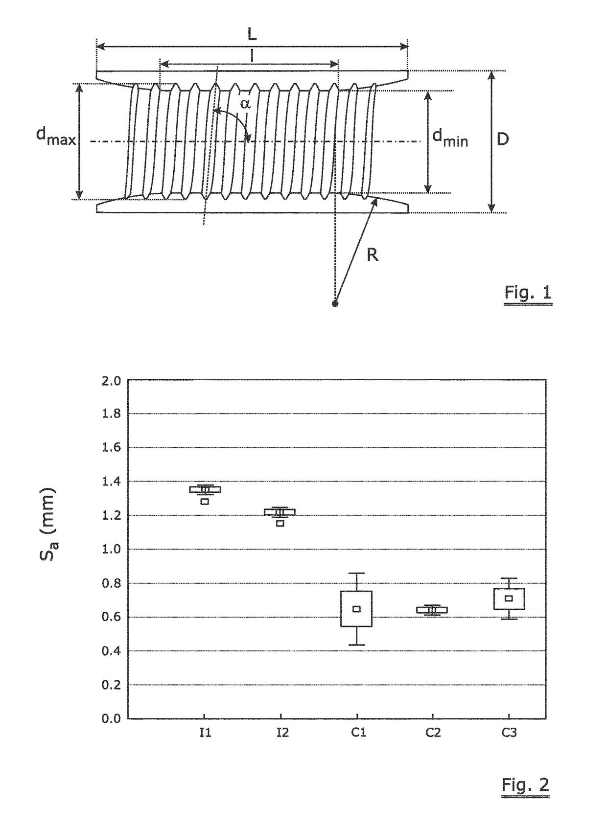
[0083]FIG. 1 shows a cross section of the inventive sleeve. The sleeve has an overall length ‘L’ and an outer diameter ‘D’. It has an axial bore with axial middle part with minimal diameter ‘dmin’ and length ‘I’. The openings at either end are chamfered and show a radius of curvature of ‘R’. The middle part is a cylinder co-axial with the axis of the sleeve. In this case the chamfering is trumpet shaped with a constant radius of curvature. When a threading is present it has a certain pitch angle denoted by ‘α’.

[0084]Five test sleeves (identified with S3.6 / ‘I’) were made of the following dimensions:[0085]‘L’=11 mm[0086]‘D’=4.98 mm[0087]‘dmin’=3.6 mm[0088]‘I’=0 (S3.610), 3 (S3.6 / 3), 5 (S3.6 / 5), 7 (S3.6 / 7) and 11 mm S3.6 / 11) (i.e. I=0×L, 0.272×L, 0.454×L, 0.636×L and 1×L)[0089]‘R’ is for the respective designs 36.22 mm (S3.6 / 0), 19.26 mm (S3.6 / 3), 10.92 mm (S3.6 / 5), 4.97 mm (S3.6 / 7) and 0 mm (S3.6 / 11)

[0090]No threading was provided to test the influence of the shape parameters. In any ...


PUM

PropertyMeasurementUnit
particle sizeaaaaaaaaaa
angleaaaaaaaaaa

Abstract

Metal sleeves are used as carriers for the abrasive layer of sawing beads. Such sawing beads are threaded on a steel cord and are separated by a polymer thus forming a sawing cord for sawing of hard and brittle materials such as stone or concrete. These metal sleeves have a large influence on the overall performance as well as on the cost of the sawing cord. The inventors propose the method of metal injection molding to make the metal sleeves in large quantities with an optimized geometry which is not possible with the current methods for making the metal sleeves. Over and above the inventive sleeves are particularly well suited for application of the abrasive layer by means of laser cladding. Beads made by laser cladding on the inventive metal sleeves as well as sawing cords comprising such beads are therefore part of the invention.

Description

[0001]The invention relates to a metal sleeve that is specifically adapted for use as the carrier sleeve of an abrasive layer in a sawing bead, the sawing bead built around such sleeve and a sawing cord using such beads. The sleeve is made by means of a metal injection moulding process that brings particular advantages for the sawing beads in its use and in its making.BACKGROUND ART[0002]Sawing cords—sometimes also referred to as sawing wires—are extensively used for sawing stones in quarries and on stationary slabbing machines. Sawing cords are for the purpose of this application understood to be an assembly of sawing beads threaded on a steel cord and spaced apart by a polymer that is injection moulded around the cord.[0003]The sawing bead itself is generally made up of a sleeve to which an abrasive layer is attached. The abrasive layer is made of a compound of metal and abrasive particles that is obtained by powder metallurgy. A mixture of metal powder and abrasive particles are ...

Claims


Application Information

Patent Timeline
Patent Type & Authority Patents(United States)
IPC IPC(8): B28D1/12B23D65/00B23D61/18B22F3/00B22F5/10B22F3/12
CPCB28D1/124B22F3/004B23D65/00B22F5/106B23D61/185B22F3/12
Inventor ZHANG, SHANNINGBAEKELANDT, TOMDECONINCK, JAN
Owner NV BEKAERT SA
Why Eureka
Try Eureka