Metal plate, method of manufacturing metal plate, and method of manufacturing deposition mask by use of metal plate

a technology of metal plate and deposition mask, which is applied in the field of metal plate, method of manufacturing metal plate, and method of manufacturing deposition mask by using metal plate, which can solve the problems of reducing affecting the luminous efficiency of the organic el display device, so as to reduce the dimensional precision of each pixel and the position precision of the pixel

Active Publication Date: 2017-11-28
DAI NIPPON PRINTING CO LTD
View PDF32 Cites 5 Cited by
  • Summary
  • Abstract
  • Description
  • Claims
  • Application Information

AI Technical Summary

Benefits of technology

[0007]When a film of a deposition material is formed on a substrate with the use of a deposition mask, the deposition material adheres not only to the substrate but also to the deposition mask. For example, some of the deposition material moves toward the substrate along a direction largely inclined with respect to a normal direction of the deposition mask. Such a deposition material reaches a wall surface of a through-hole of the deposition mask and adheres thereto, before it reaches the substrate. In this case, the deposition material is not likely to adhere to an area of the substrate, which i

Problems solved by technology

Namely, the deposition near the wall surface of the through-hole of the deposition mask may become unstable.
Thus, when this deposition mask is used for forming pixels of an organic EL display device, dimensional precision of each pixel and positional precision thereof lower, which lowers luminous efficiency of the organic EL display device.
Whe

Method used


Image

  • Metal plate, method of manufacturing metal plate, and method of manufacturing deposition mask by use of metal plate
  • Metal plate, method of manufacturing metal plate, and method of manufacturing deposition mask by use of metal plate
  • Metal plate, method of manufacturing metal plate, and method of manufacturing deposition mask by use of metal plate

Examples


examples

[0177]Next, although the present invention is described in more detail referring to examples, the present invention is not limited to the below examples as long as it departs from the scope of the present invention.

[0178](First Winding Body and First Sample)

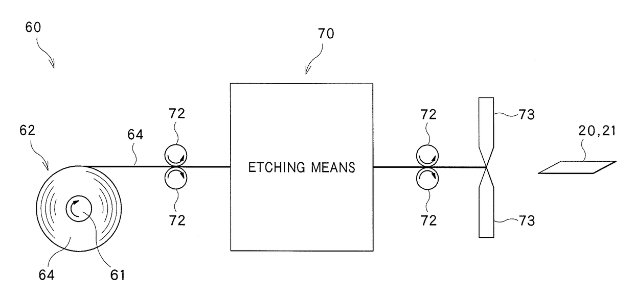
[0179]Firstly, by performing the aforementioned rolling step, the slitting step, the annealing step and the cutting step were performed to the base metal made of the invar alloy, a winding body (first winding body) around which an elongated metal plate was wound was manufactured.

[0180]To be specific, a first rolling step, in which a first hot rolling step and a first cold rolling step were performed in this order, was firstly performed. Then, a first slitting step, in which both ends in the width direction of the elongated metal plate were slit over a range of not less than 3 mm and not more than mm, respectively, was performed. Thereafter, a first annealing step, in which the elongated metal plate was continuously annealed at 50...


PUM

PropertyMeasurementUnit
Temperatureaaaaaaaaaa
Fractionaaaaaaaaaa

Abstract

The object of the present invention is to provide a metal plate capable of manufacturing a deposition mask in which dispersion of positions of through-holes is restrained. A thermal recovery rate is defined as parts per million of a difference a distance between to measurement points on a sample before a heat treatment and a distance therebetween after the heat treatment, relative to the distance therebetween before the heat treatment. In this case, an average value of the thermal recovery rates of the respective samples is not less than −10 ppm and not more than +10 ppm, and (2) a dispersion of the thermal recovery rates of the respective samples is not more than 20 ppm.

Description

BACKGROUND OF THE INVENTION[0001]Field of the Invention[0002]The present invention relates to a metal plate for use in manufacturing a deposition mask with a plurality of through-holes formed therein. In addition, the present invention relates to a method of manufacturing the metal plate. In addition, the present invention relates to a method of manufacturing the mask with a plurality of through-holes formed therein, by use of the metal plate.[0003]Background Art[0004]A display device used in a portable device such as a smart phone and a tablet PC is required to have high fineness, e.g., an image density not less than 300 ppi. In addition, there is increasing demand that the portable device is applicable in the full high-definitions standard. In this case, the image density of the display device needs to be 450 ppi or more.[0005]An organic EL display device draws attention because of its excellent responsibility and low power consumption. A known method of forming pixels of an organ...

Claims


Application Information

Patent Timeline
IPC IPC(8): B44C1/22C23F1/02C23F1/00C23C14/04C21D6/00C21D8/00
CPCC23C14/042C21D6/001C23F1/02C23F1/00C21D2261/00C21D8/00C23F1/28C23F1/04B21B45/004H10K71/166H10K50/10C21D8/005
Inventor IKENAGA, CHIKAOMIYATANI, ISAO
Owner DAI NIPPON PRINTING CO LTD
Why Eureka
Try Eureka