Method of configuring lighting effect patterns for interactive lighting effect devices

a technology of lighting effect and lighting pattern, which is applied in the direction of instruments, semiconductor lamp usage, sensing by electromagnetic radiation, etc., can solve the problems of illuminating color blotches or anomalies, affecting the performance of interactive lighting effect devices, and occupying a long time for completion, so as to improve the dynamic or improvisational lighting effect changes, enhance the performance capability and functionality of interactive lighting effect devices, and improve the effect of lighting effect changes.

Active Publication Date: 2018-03-06
LUMIC TECH INC
View PDF28 Cites 1 Cited by
  • Summary
  • Abstract
  • Description
  • Claims
  • Application Information

AI Technical Summary

Benefits of technology

[0008]The present invention provides that a total number of the interactive lighting effect device can be one or more, and that the interactive lighting effect control system can efficiently and effectively manage and handle a large number of the interactive lighting effect devices upwards of a million or more.
[0028]Some of the advantages of the interactive lighting effect device configured to be operating in an integrated and coordinated illuminating environment to produce continuous dynamic visual effects on a mass scale using the interactive lighting effect control system of present invention, include: (a) reducing configuration cost and improving efficiency for configuring of each interactive lighting effect device to be ready for usage prior to each lighting effect show; (b) none of pre-programmed LED illumination light control sequences as well as the zone code according to seating location need to be pre-stored inside the memory of any interactive lighting effect device ahead of time before an lighting effect show / presentation; (c) a lighting effect performance for an entire venue event having plenty of sophisticated or intricate illuminating sequences would only a small amount of zone code data to be pre-stored in the memory of the interactive lighting effect device for implementing various surprise or improvisational lighting changes; (d) any lighting or illumination change can be integrated on the fly on top of or manually overriding the pre-programmed LED illumination sequences at any time using a DMX lighting controller; (e) having more efficient and convenient zone assignment capability for each interactive lighting effect device using the interactive lighting effect control system.

Problems solved by technology

Upon completion of the above-mentioned programming configurations of each of the interactive lighting effect devices, they are required to be transported or shipped to the concert or event venue, whereby they are required to be placed one-by-one by hand at each of many assigned seating locations, respectively, and thus would take up a long time for completion.
Furthermore, any accidental misplacement or incorrect placement of any lighting effect device, i.e. an interactive light effect device belonging to seating zone B, row 6, seat number 2 misplaced to end up at seating zone B, row 7, seat 2, will lead to a lighting effect show having inferior or deteriorated visual quality by creating illuminating color blotches or anomalies.
Moreover, because all of the lighting effect pattern sequence data had already being written into the memory of each interactive lighting effect device ahead of time during the manufacturing phase thereof and also that the configuring / programming of the lighting effect pattern sequence data requires to be performed under a tedious manual process (instead of an efficient automated process) requiring a lot of manpower, as a result, any spontaneous or dynamic illuminating effect changes cannot be realized or updated in time during the lighting effect show at the venue event.
In addition, because the wrists have to be grouped in according to one corresponding zone region at the kiosk, thus severely limiting entry convenience for venue attendees when desiring to reach different zone regions inside the venue event when entering at one entry point.

Method used


Image

  • Method of configuring lighting effect patterns for interactive lighting effect devices
  • Method of configuring lighting effect patterns for interactive lighting effect devices
  • Method of configuring lighting effect patterns for interactive lighting effect devices

Examples


first embodiment

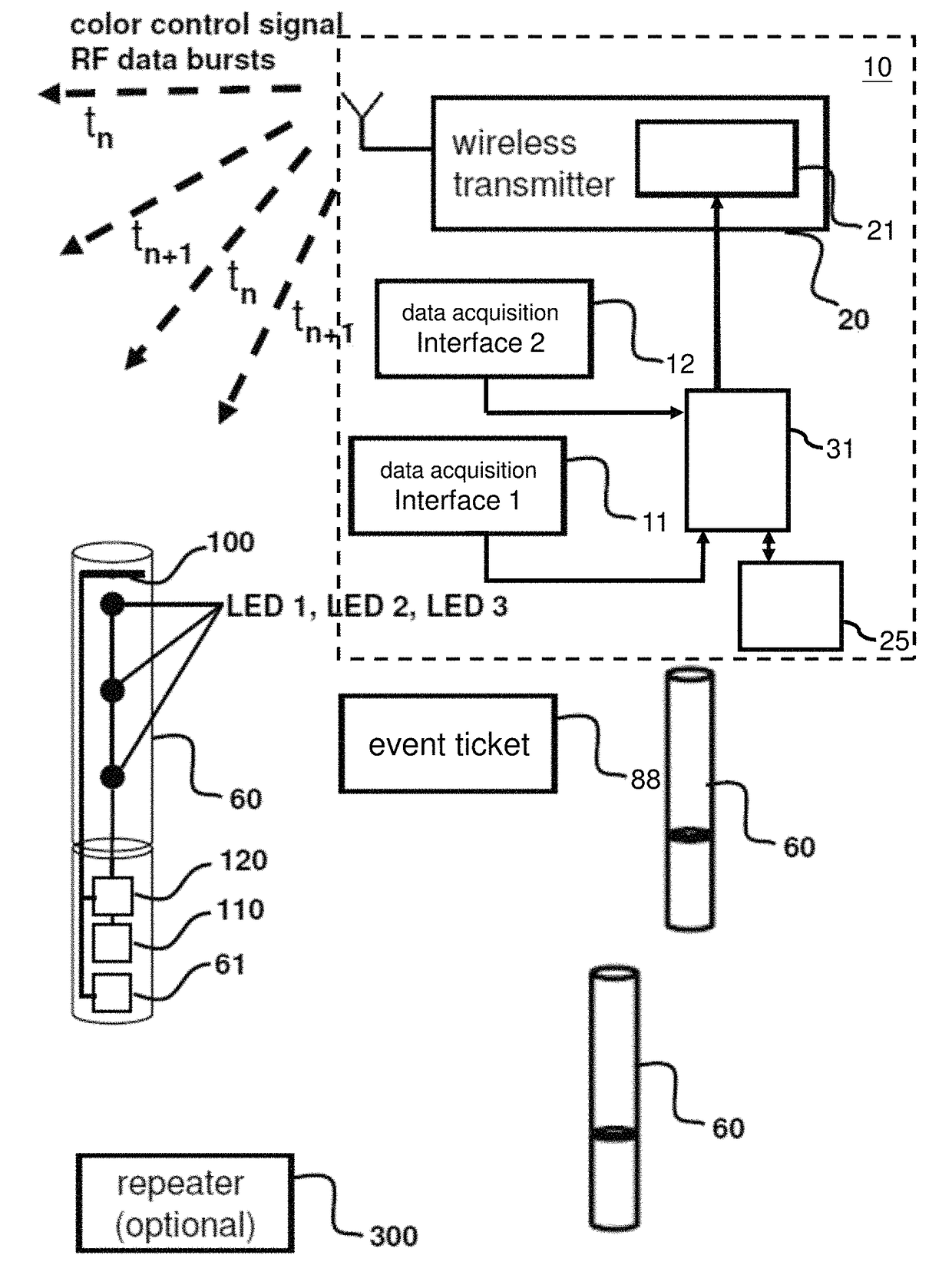
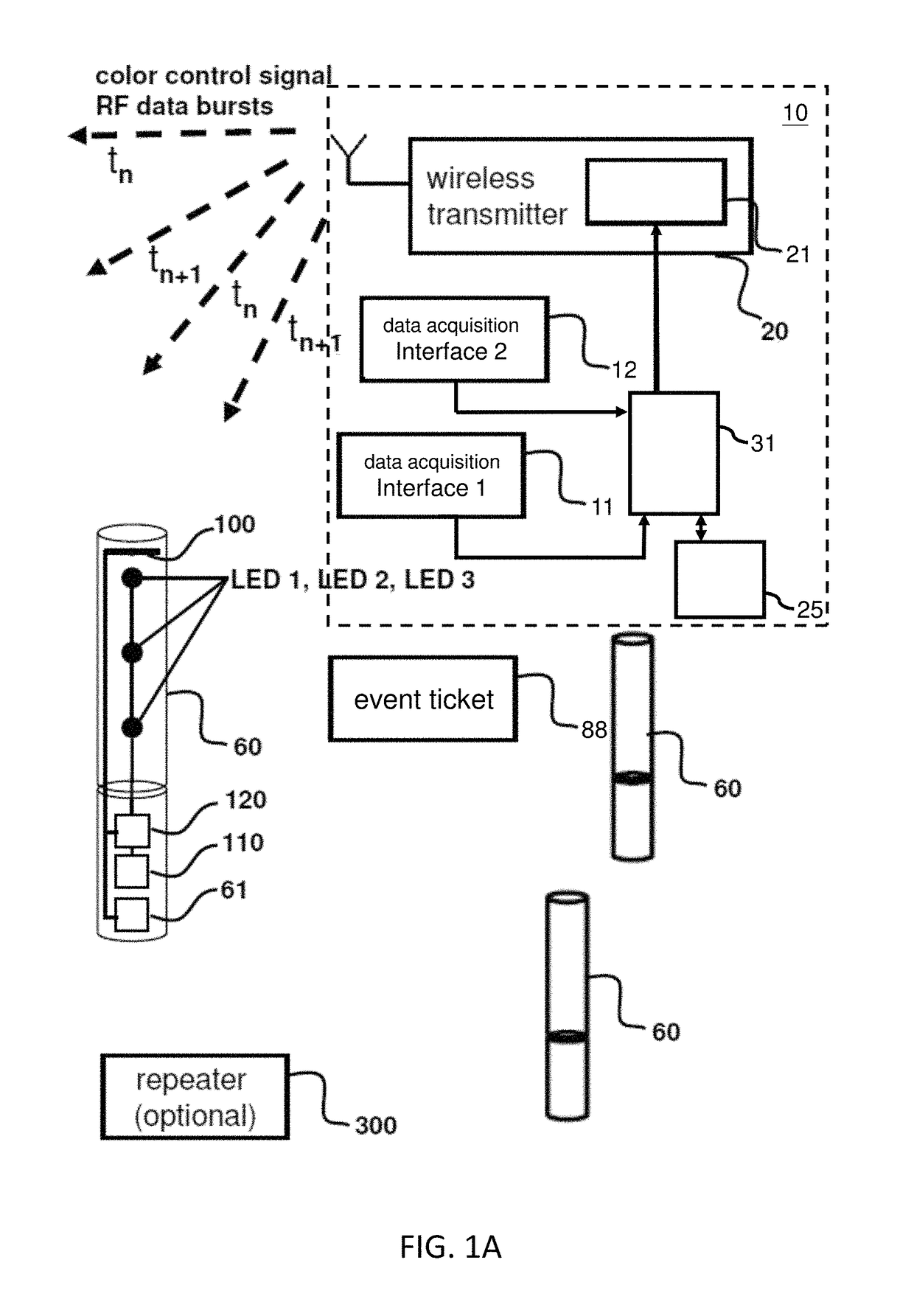
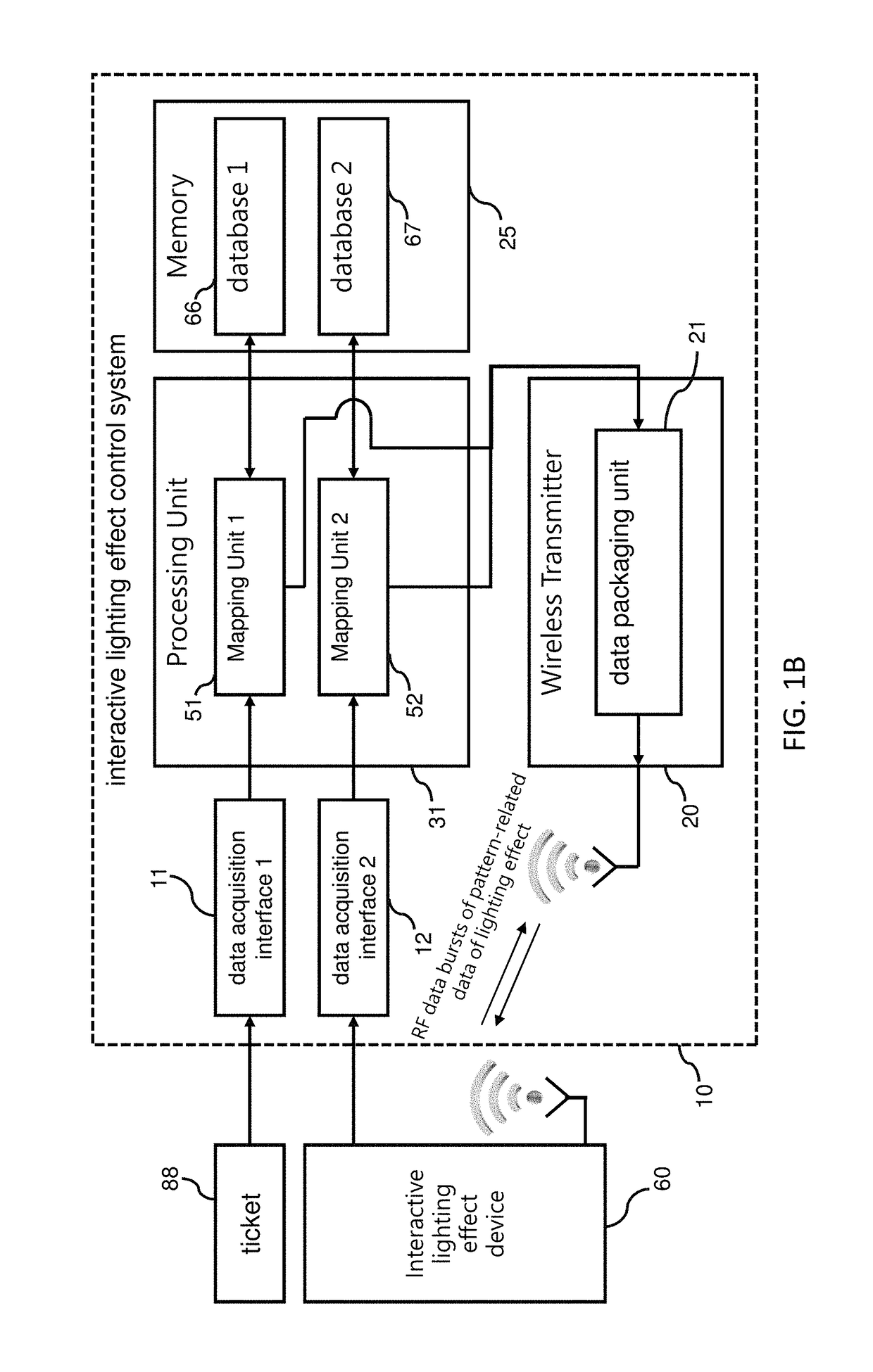
[0044]As shown in a block diagram in FIGS. 1A-1B, an interactive lighting effect control system 10 (which can be referred to as a programming system, for short) configured and adapted for use together with a plurality of interactive lighting effect devices 60 and one or more event tickets 88 in accordance with present invention is shown. The interactive lighting effect control system 10 includes a first data acquisition interface 11, a second data acquisition interface 12, a wireless transmitter 20, a memory 25, and a processing unit 31. The wireless transmitter 20 can be realized or provided by an RF transmitter chip together with other accessory electronic components, such as, for example, Texas Instrument model number CC2541 or CC2500 RF transceiver. The first data acquisition interface 11 and the second data acquisition interface 12 can be a QR code / barcode scanner, respectively. Alternatively, a RFID reader or NFC reader can be used as the data acquisition interface for extract...

second embodiment

[0045]As shown in a block diagram in FIG. 2, an interactive lighting effect control system (which can be referred to as a programming system for the mobile device, for short) configured and adapted for use together with a plurality of interactive lighting effect devices 60 and one or more event tickets 88 in accordance with present invention is shown. The interactive lighting effect control system includes a mobile device 9, and the mobile device 9 includes a first data acquisition interface 11, a second data acquisition interface 12, a wireless transmitter 22, a memory 26, and a processing unit 32. The wireless transmitter 22 can be realized or provided by preconfigured RF transmitter chip together with other accessory electronic components disposed inside the mobile device 9. The mobile device 9 can be for example, a smartphone equipped with a camera (not shown) and configured with a QR code / barcode reader app to provide the functions as the first data acquisition interface 11 and...

third embodiment

[0068]In present invention, the processing unit can be the application processor of the mobile device, or an embedded system, such as for example, Raspberry Pi, to control the process flow for the first mapping unit and the second mapping unit.

[0069]In the embodiments of present invention, both of the first mapping unit and the second mapping unit can be part of the programmed flow of the processing unit. In the first and the second embodiments, the first mapping unit and the second mapping unit can also be two independent MCUs, such as for example, the Silicon Labs 32 bits MCU Cortex M4. Alternatively, the first mapping unit and the second mapping unit can also be two independent embedded system, such as for example, Raspberry Pi.

[0070]In the embodiments of present invention, the data packaging unit disposed inside the wireless transmitter, can belong as part of the programmed flow of the wireless transmitter, or the data packaging unit can be an independent MCU, such as for exampl...


PUM


Abstract

Interactive lighting effect devices configured by an interactive lighting effect control system in an automated wireless manner on a mass scale are provided. RF data bursts are captured to illuminate interactive lighting effect devices selectively in accordance with a matched data. The matched data is formed by combining a pattern-related data of lighting effect extracted from a QR code of the event ticket with an identification address extracted from a QR code of the interactive lighting effect device, the pattern-related data of lighting effect includes a zone code. Improvisational illuminating color control change for any zone assignment for color control signal can be generated and converted to set of RGB color codes to be transmitted by the interactive lighting effect control system for broadcasting as data bursts to the interactive lighting effect devices. Different types of data acquisition interfaces are provided for obtaining the matched data.

Description

FIELD OF THE INVENTION[0001]The present invention generally relates to a method for a process for configuring lighting effect patterns for interactive lighting effect devices and, more particularly, to a process comprising of steps for dynamically and interactively configuring lighting effect patterns for one or more interactive lighting effect devices located at an event venue to produce dynamic and interactive lighting effects on a mass scale.BACKGROUND OF THE INVENTION[0002]Interactive lighting effective devices, such as, for example, handheld LED glow sticks are popular portable electronic devices used for achieving interactive mass-scaled lighting effects in various venue events or mass gatherings, such as at a musical concert, a sporting event, a mass gathering, a church event, a political gathering, an educational institution convention, when the interactive lighting effect devices are being operated in a coordinated illuminating patterns to produce continuous illuminating vi...

Claims


Application Information

Patent Timeline
Patent Type & Authority Patents(United States)
IPC IPC(8): H05B33/08H05B37/02G06K7/14H05B44/00
CPCH05B33/086H05B37/0272G06K7/1417H05B45/20H05B47/155H05B47/19Y02B20/30
Inventor LU, YING-KOHUANG, TA-WEILIN, TA-JENCHANG, CHIH-MINGWANG, WEN-CHIH
Owner LUMIC TECH INC
Why Eureka
Try Eureka