Switching device for a motor vehicle transmission and method for actuating a motor vehicle transmission

a technology for motor vehicles and transmissions, which is applied in the direction of transmission elements, belts/chains/gearrings, toothed gearings, etc., can solve the problems of disadvantageous effect on transmission efficiency, construction complexity and heavy, and achieve reliable torque transmission, low cost, and low cost

Active Publication Date: 2018-04-10
HOERBIGER ANTRIEBSTECHN HLDG
View PDF10 Cites 4 Cited by
  • Summary
  • Abstract
  • Description
  • Claims
  • Application Information

AI Technical Summary

Benefits of technology

[0005]This is achieved in a switching device including a coupling component, several transmission shafts which each are rotatable about a transmission axis, a frictional contact ring including a friction cone and being substantially non-rotatably and axially shiftably connected with a transmission shaft, a form-fit ring including a cone surface and being substantially non-rotatably and axially shiftably connected with the coupling component, as well as an actuating body including a cone surface and being substantially non-rotatably and axially shiftably connected with the coupling component. The friction cone of the frictional contact ring extends between the cone surface of the form-fit ring and the cone surface of the actuating body. The transmission shaft and the coupling component are decoupled in direction of rotation in an axial starting position of the actuating body, frictionally coupled in direction of rotation in an axial frictional contact position of the actuating body and positively coupled in direction of rotation in an axial form-fit position of the actuating body. The form-fit ring in a form-fit position is positively connected with the transmission shaft and in a release position is not positively connected with the transmission shaft. The form-fit ring is axially movable between its form-fit position and its release position and is urged into the release position. In functional terms, the switching device thus is a cone clutch with form-fit engagement, wherein the components to be coupled preferably are urged into a decoupled starting position. As compared to a conventional multidisk clutch, such switching device is constructed distinctly more compact and can be actuated in a considerably more energy-efficient manner. Since in the decoupled condition of the switching device the maximum torque to be transmitted can be transmitted by form-fit engagement, less friction points are required as compared to a conventional multidisk clutch, which leads to a distinct reduction of the drag torques and hence has a positive influence on the transmission efficiency. The frictional contact position of the actuating body preferably is located axially between the starting position and the form-fit position of the actuating body and forms a kind of axial intermediate position into which the actuating body can be moved with comparatively little energy expenditure. For numerous load cases, however, a torque transmission capacity of the switching device in the frictional contact position of the switching device already is sufficient for torque transmission, so that no further movement of the actuating body into its form-fit position is necessary. This also has a positive influence on the transmission efficiency. Merely in load cases with very high torque load is the actuating body moved into its form-fit position with further energy expenditure, in order to increase the torque transmission capacity of the switching device.

Problems solved by technology

The coupling of individual planetary gearset elements at present mostly is effected by means of multidisk clutches which, however, are constructionally complex and heavy as well as require an undesirably large installation space.
Due to the numerous friction points, the undesired drag torques are quite high in the decoupled condition and have a disadvantageous effect on the transmission efficiency.

Method used


Image

  • Switching device for a motor vehicle transmission and method for actuating a motor vehicle transmission
  • Switching device for a motor vehicle transmission and method for actuating a motor vehicle transmission
  • Switching device for a motor vehicle transmission and method for actuating a motor vehicle transmission

Examples


Embodiment Construction

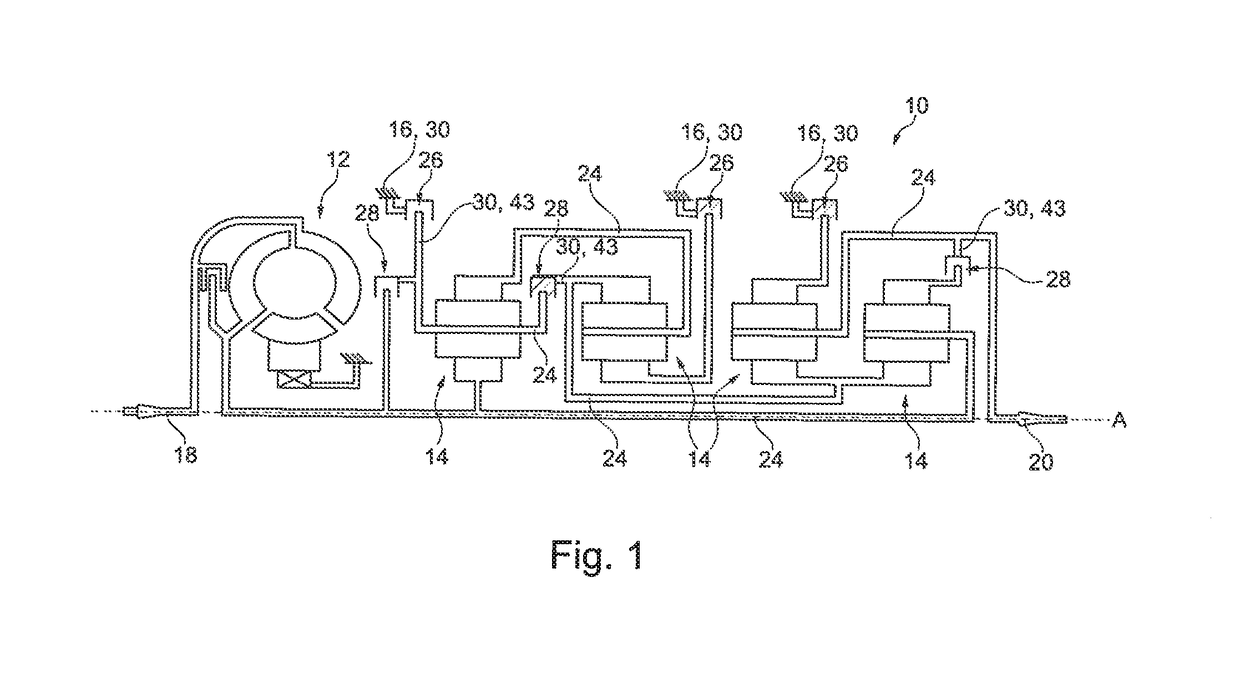
[0041]FIG. 1 shows an electrohydraulically actuated, fully automatic stepped transmission 10 of a motor vehicle with a torque converter 12, four planetary transmissions or planetary gearsets 14 and a schematically indicated transmission housing 16. Furthermore a drive shaft 18, a driven shaft 20 and several transmission shafts 24 are provided, wherein in the following planetary gear carriers also are referred to as transmission shafts 24. The transmission shafts 24 are associated to the individual planetary gearsets 14 and arranged coaxially to each other.

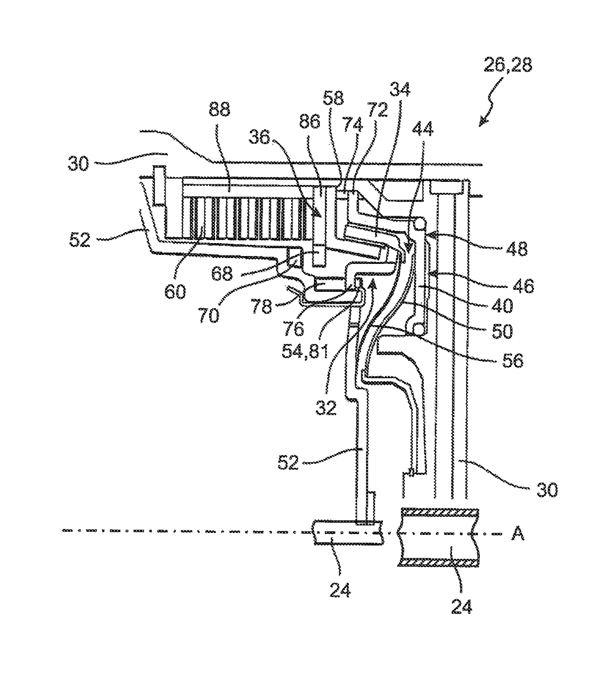
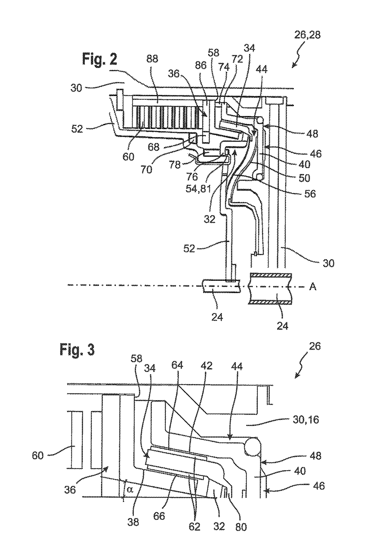
[0042]The stepped transmission 10 in addition includes switching devices 26, 28, to which a hydraulic pressure can be applied and which can couple a transmission shaft 24 either with a further transmission shaft 24 or with the transmission housing 16 or can decouple the transmission shaft 24 from the further transmission shaft 24 or the transmission housing 16.

[0043]A switching device 26, which couples the transmission shaft 24 wit...


PUM


Abstract

A switching device for a motor vehicle transmission includes a coupling component, several transmission shafts which each are rotatable about a transmission axis, a frictional contact ring including a friction cone and being substantially non-rotatably and axially shiftably connected with a transmission shaft, a form-fit ring including a cone surface and being substantially non-rotatably and axially shiftably connected with the coupling component, as well as an actuating body including a cone surface and being substantially non-rotatably and axially shiftably connected with the coupling component. The friction cone of the frictional contact ring extends between the cone surface of the form-fit ring and the cone surface of the actuating body. The transmission shaft and the coupling component are decoupled in direction of rotation in an axial starting position of the actuating body, frictionally coupled in direction of rotation in an axial frictional contact position of the actuating body and positively coupled in direction of rotation in an axial form-fit position of the actuating body. The form-fit ring in a form-fit position is positively connected with the transmission shaft and in a release position is not positively connected with the transmission shaft. The form-fit ring is axially movable between its form-fit position and its release position and is urged into the release position. In addition, a method for actuating a motor vehicle transmission is provided.

Description

TECHNICAL FIELD[0001]This invention relates to a switching device for a motor vehicle transmission, in particular for a fully automatic stepped transmission, and to a method for actuating a motor vehicle transmission.BACKGROUND OF THE INVENTION[0002]In automotive engineering, automatic transmissions, in particular stepped fully automatic transmissions with hydrodynamic torque converter and planetary transmissions are used for power transmission beside manual variable-speed transmissions.[0003]Such fully automatic stepped transmissions act as powershift transmissions without interruption of the tractive force, wherein the power flow is effected via planetary gearsets and the gear changes occur by coupling or releasing individual planetary gearset elements. The coupling of individual planetary gearset elements at present mostly is effected by means of multidisk clutches which, however, are constructionally complex and heavy as well as require an undesirably large installation space. S...

Claims


Application Information

Patent Timeline
Patent Type & Authority Patents(United States)
IPC IPC(8): F16D23/06F16D23/04F16D63/00F16H3/66
CPCF16D23/04F16D63/006F16H2200/2046F16H3/66F16H2200/2012F16D2023/0681
Inventor DAMM, ANSGARECHTLER, PETERKOELZER, MICHAELACKERMANN, JUERGENLUNDIN, KJELL
Owner HOERBIGER ANTRIEBSTECHN HLDG
Why Eureka
Try Eureka