LED light

a technology of led light and diodes, which is applied in the direction of lighting and heating apparatus, semiconductor devices for light sources, and support devices for lighting, etc., can solve the problems of difficult mass production of led light, energy consumption and heat dissipation, and the development of led lighting technology still has challenges, so as to achieve better heat dissipation, more energy efficiency, and high brightness

Active Publication Date: 2016-01-07
NANOGRID
View PDF3 Cites 16 Cited by
  • Summary
  • Abstract
  • Description
  • Claims
  • Application Information

AI Technical Summary

Benefits of technology

[0061]Accordingly, the LED bulb of the invention is structurally different from the LED bulb in prior art, because the LED bulb of the invention uses a whole PCB with bending lines thereon to form a LED bulb body, and changes the traditional structure of the LED lamp. The LED bulb of the present invention is not easy to be broken, and would not result in harm to those who use it. Moreover, the LED bulb of the present invention is much more energy efficient and higher brightness than traditional lamps.
[0062]Each LED in the LED bulb of the present invention has a heat sink pad cooperated with the metal layer of PCB, preferably a copper layer, so that the heat dissipating is transferred from the LED chips to the metal layer of the PCB. This allows the PCB to act as a heat sink for the LEDs. This enables heat dissipation better than other LED bulb, which would increase the lifetime of the LED bulb of the present invention.
[0063]In addition, by virtue of the 3-D structure of the LED bulb, such as a hendecahedron and a dodecahedron shape, the appearance of the LED bulb is more attractive which may be spread and accepted by the market soon. And more important is that at least one LED is mounted on each face of the 3-D structured polyhedron, which would render omnidirectional light-emitting from the LED bulb, thereby obtaining better illumination in a room or a house.

Problems solved by technology

The development of LED lighting technology still has challenges, including energy consumption and heat dissipation.
Mass production of this kind of LED light is difficult due to its costly manufacturing processes and assembly.
As such, while less power will be required to achieve the same lumen output, the light will employ more LEDs, which is more expensive.
Most prior art LED lighting overdrives the LEDs which requires less LEDs per light and increases heat dissipation challenges, which are resolved with fans and complex heat fin systems.
Significantly, overdriving LEDs reduces the luminous efficacy or efficiency of the light, measured as lumens per watt (lm / W), since a higher current is driven through an LED which is rated for a relatively lower normal rating.
Furthermore, overdriving the LEDs will reduce their useful operating life, sometimes significantly if head dissipation is not accordingly enhanced.
Manufacturers have experienced much difficulty in improving the efficiency of 100 W replacement LED bulbs, in part due to the heat dissipation problems.

Method used


Image

  • LED light
  • LED light
  • LED light

Examples


assembly example 1

Bottom to Top

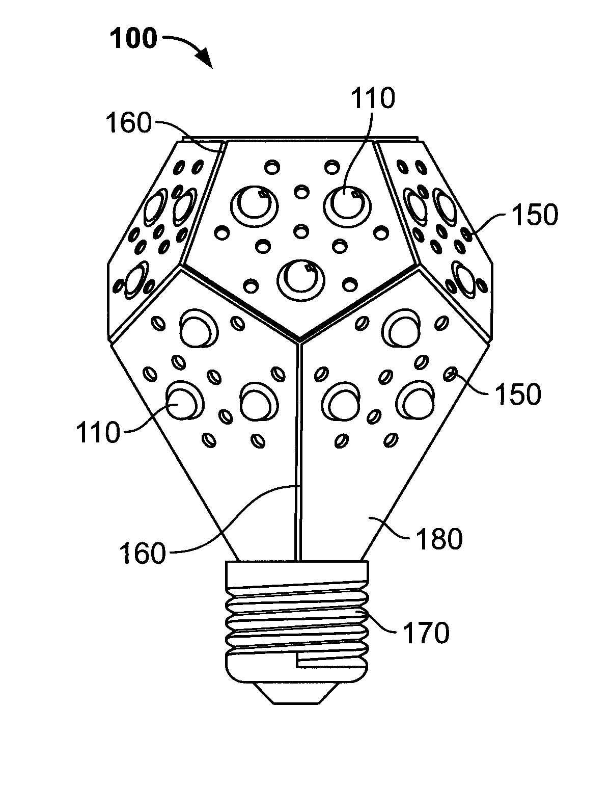
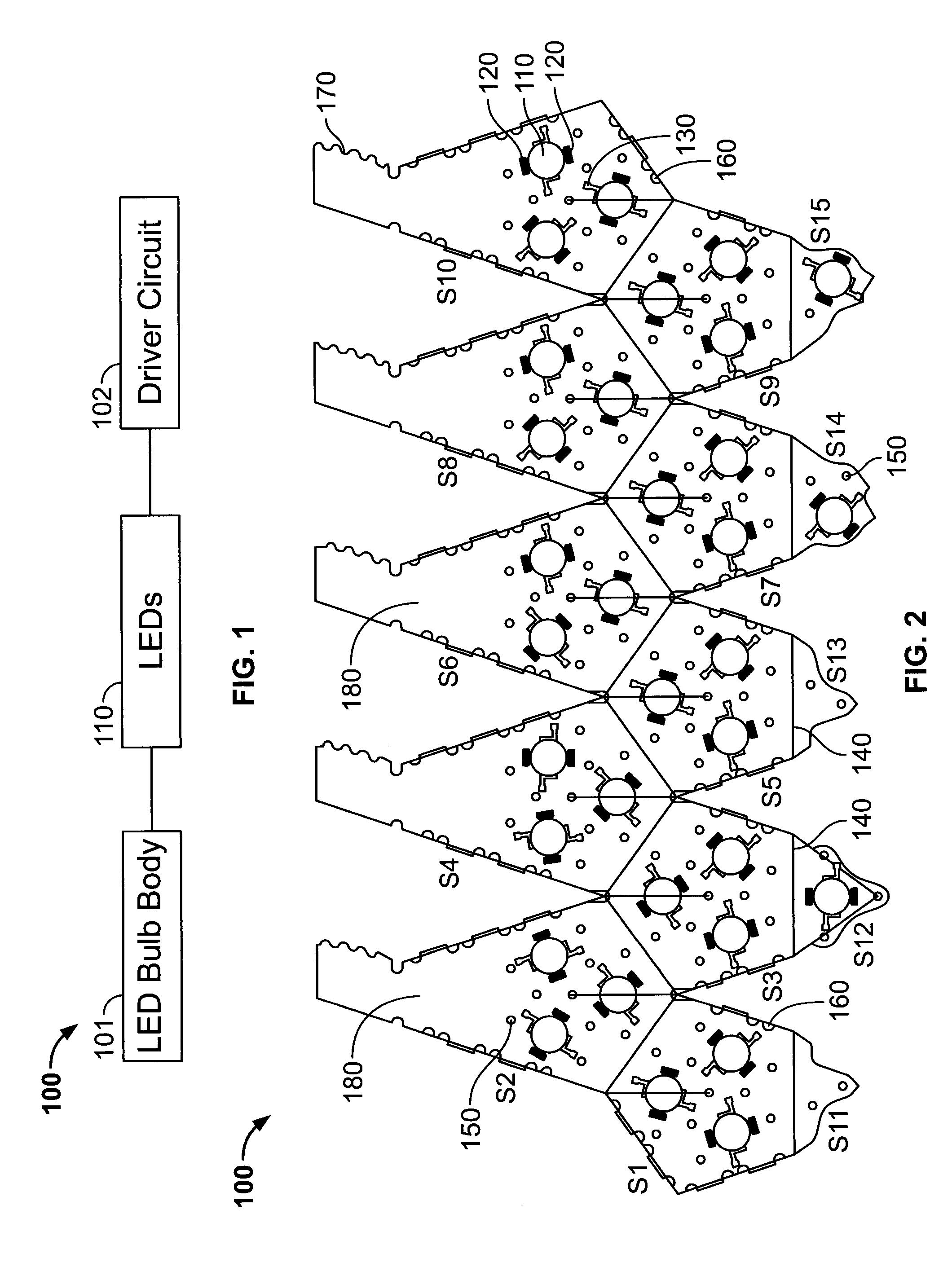
[0194]The following assembly instructions are with reference to the PCB template of FIG. 13A. The assembly can be referred to as a “bottom to top assembly” as the top face is the final part to be assembled. For ease of illustration, all the internal components are not illustrated when teaching the assembly. A non-energized plate, such as a non-conductive PCB template 1310 of FIG. 12 is used, along with a light fitting and instant glue. 3M glue was used in one embodiment. Using instant glue on the joining surfaces, attach the non-conductive plate 1310 to the PCB structure as shown in FIG. 13B. With reference to FIG. 2, non-conductive plate 1310 is adhered onto shape S12 in this example.

[0195]FIG. 13C illustrates the steps of assembly along with these instructions. FIG. 13C shows fold lines, edges, and surfaces. Starting with an angle of 180 degrees between surfaces, fold about 63 degrees along bending line 1 to reach an angle of about 117 degrees between surfaces. Make s...

assembly example 2

Top to Bottom

[0200]The following assembly instructions are with reference to the PCB template of FIG. 10. The assembly can be referred to as a “top to bottom assembly” as the final assembly step occurs at the bottom when the light fitting is attached. For ease of illustration, all the internal components are not illustrated when teaching the assembly.

[0201]In this embodiment, a non-conductive plate such as the non-conductive plate 1310 of FIG. 12 is not required. In addition to the star-shaped PCB template, a light fitting and instant glue are required.

[0202]FIG. 14 illustrates the steps of assembly along with these instructions. FIG. 14 shows fold lines, interlocking edge teeth, and screw threads. Starting with an angle of 180 degrees between surfaces, fold about 63 degrees along bending line 1 to reach an angle of about 117 degrees between surfaces. Make similar folds at bending lines 2, 3, 4 and 5. 3. Align and lock the interlocking edges A, B, C, D, and E. Fold about 63 degrees ...


PUM


Abstract

An LED bulb comprises a structural shell formed by folding a flat PCB into a three-dimensional polyhedron shape and a fitting for removably coupling the bulb to a light socket. The PCB comprises a plurality of LEDs, at least one LED mounted electronically on a plurality of faces of the polyhedron, and a driver circuit for driving each LED. The perimeter of the PCB is shaped to join adjacent faces. Each LED produces minimal excess heat, which is partially conducted by a metallic heat sink bridge to the PCB and dissipated to the air through the PCB and through a plurality of spaces in the shell.

Description

TECHNICAL FIELD[0001]The present invention generally relates to an LED (light emitting diode) illumination device, and more particularly, to a light bulb which is fabricated by folding a two-dimensional printed circuit board (PCB) with LEDs mounted thereon into a three-dimensional structure. The three dimensional structure is configured to fit into a standard light fitting.BACKGROUND OF THE INVENTION[0002]LED lighting has gradually gained traction in a market once dominated by traditional lighting products such as incandescent light bulbs due to several advantages, including lower energy consumption and higher brightness. The development of LED lighting technology still has challenges, including energy consumption and heat dissipation.[0003]Many LED lights are disclosed in the prior art. For example, Chinese Patent Publication No. 101749675A and United Kingdom Patent Publication No. 2467027 disclose an LED light assembly which includes a plurality of LED PCBs, with each PCB having a...

Claims


Application Information

Patent Timeline
Patent Type & Authority Applications(United States)
IPC IPC(8): F21V29/74F21K99/00F21V23/00F21V23/06F21V29/83
CPCF21V29/74F21K9/1355F21Y2101/02F21V23/005F21V29/83F21V23/06
Inventor RODINGER, TOMASCHU, GIMMYYAN, CHRISTIAN
Owner NANOGRID
Why Eureka
Try Eureka