Power transmission assembly for a vehicle

a technology for power transmission and vehicle, applied in fluid gearings, transportation and packaging, gearing, etc., can solve the problems of increasing the cost of manufacturing the power distribution unit, complicated power directive conversion mechanism, and increasing the cost of power distribution unit manufacturing, so as to reduce the number of parts and the effect of cost reduction

Inactive Publication Date: 2018-04-17
KANZAKI KOKYUKOKI MFG
View PDF4 Cites 0 Cited by
  • Summary
  • Abstract
  • Description
  • Claims
  • Application Information

AI Technical Summary

Benefits of technology

[0016]Therefore, even if an input shaft of the power distribution unit is extended coaxially or parallel to the prime mover output shaft and is drivingly connected to the prime mover output shaft via a sleeve or a belt, an economic and simple mechanism, such as spur gears or pulleys and a belt, can be used to transmit power from the input shaft of the power distribution unit to the pump shafts of the right and left transmission units. Therefore, the power distribution unit has a simple structure such as to reduce costs for its manufacturing. Further, in comparison with the bevel gears, the spur gears reduce power loss, thereby reducing fuel costs. Further, the arrangement of the pump shafts parallel to the prime mover output shaft reduces a lateral width of the power distribution unit, thereby reducing a lateral width of a vehicle equipped with the power transmission assembly. Further, the separation of the hydraulic pumps from the power distribution unit enhance the freedom in arrangement and design of the right and left transmission units, so that the power transmission assembly can be freely modified to correspond to another vehicle having a different lateral width or having an engine at a different position.
[0020]Therefore, the speed reduction device is configured as a hypocycloid gear mechanism that ensures a sufficient reduction ratio while it is minimized in the radial direction and has a simple structure.
[0022]Therefore, the power transmission assembly does not need another support member than the speed reduction devices of the right and left transmission units, thereby reducing parts in number and in cost.

Problems solved by technology

As mentioned above, the power directive conversion mechanism is complicated and expensive because it includes the bevel gears on the input shaft and on the pump shafts, thereby complicating the structure of the power distribution unit, and increasing costs for manufacturing the power distribution unit.
Further, the bevel gears serving as the power directive conversion mechanism cause an increase in power loss, thereby increasing fuel costs.

Method used


Image

  • Power transmission assembly for a vehicle
  • Power transmission assembly for a vehicle
  • Power transmission assembly for a vehicle

Examples


Embodiment Construction

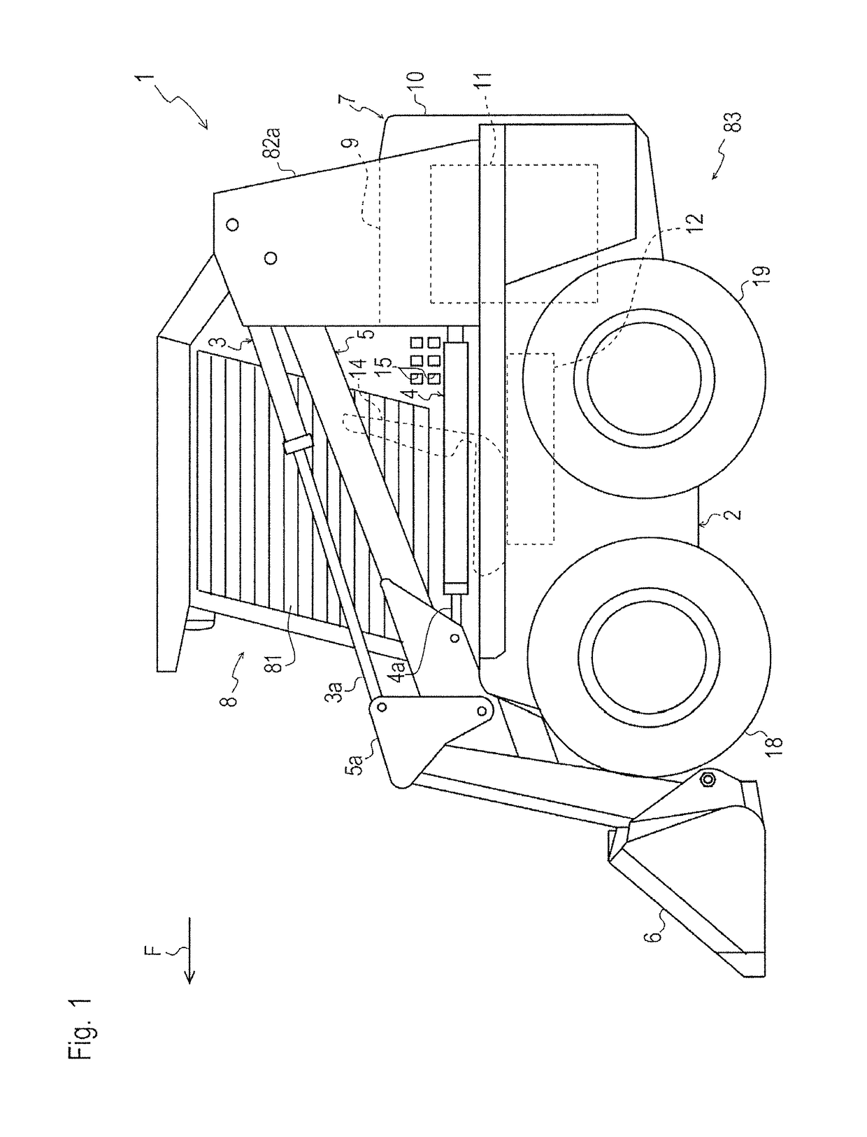
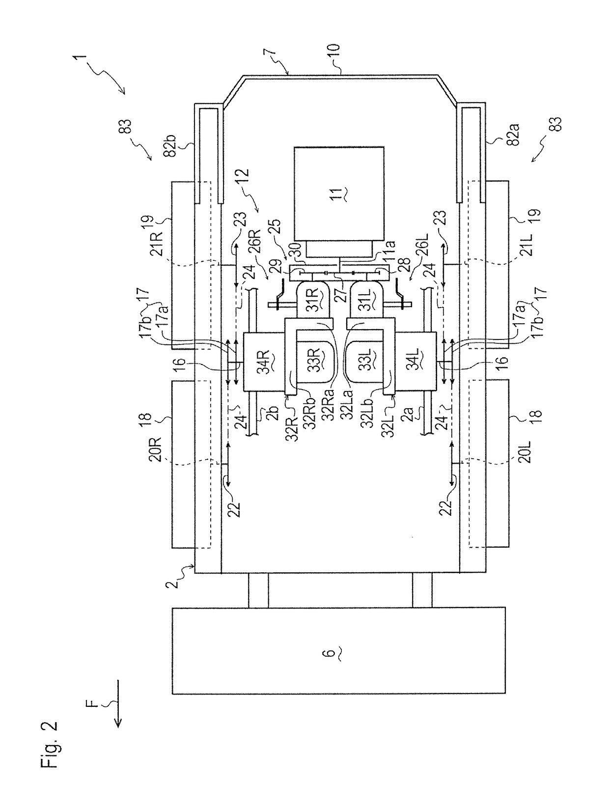
[0039]A skid steer loader 1 shown in FIG. 1 is assumed to face forward as designated by an arrow F in FIG. 1. Another later-discussed track loader 90 shown in FIG. 9 is also assumed to face forward as designated by arrow F in FIG. 9. All the following descriptions of components of loaders 1 and 90 with reference to all the other drawings will be given on the assumption that arrow F in each drawing designates the forward direction of loader 1 or 90.

[0040]Further, words “proximal” and “distal” will be used on an assumption that if there are any two members or portions at different positions in the lateral direction of loader 1 or 90, one closer to the lateral center of loader 1 or 90 is defined as being “proximal”, and another farther from the lateral center of loader 1 or 90 is defined as being “distal”.

[0041]Skid steer loader 1 will be described with reference to FIGS. 1 to 3. Right and left pillars 82a and 82b are provided on a rear upper portion of a chassis 2 of skid steer loader...


PUM


Abstract

A power transmission assembly for a vehicle with prime mover, prime mover output shaft, and right and left traveling devices, comprises a power distribution unit that receives rotary power from the prime mover output shaft and distributes it between right and left transmission units, which each include: a center section with a closed fluid circuit, a lateral first portion, and a second portion perpendicular thereto; a hydraulic pump mounted on the first portion such that a pump shaft is parallel to the prime mover output shaft; a hydraulic motor on the second portion fluidly connected to the hydraulic pump via the closed fluid circuit, having a lateral motor shaft; and a speed reduction device on a distal side of the hydraulic motor that transmits power from the hydraulic motor to the right or left traveling device.

Description

CROSS-REFERENCE TO RELATED APPLICATIONS[0001]The present application claims priority to Japanese Patent Application No. 2014-056785, filed on Mar. 19, 2014.BACKGROUND OF THE INVENTION[0002]1. Field of the Invention[0003]The present invention relates to a power transmission assembly for a vehicle.[0004]2. Related Art[0005]As disclosed by U.S. Pat. No. 8,327,639 B, there is a well-known conventional working vehicle, such as a lawn mower, a skid steer loader, or a track loader, which is equipped with an engine, and right and left traveling devices driven by power of the engine. The driving directions and speeds of the respective right and left traveling devices are individually controlled for turning the vehicle, instead of a steering mechanism. Typical right and left traveling devices use right and left drive wheels or crawlers.[0006]The vehicle is equipped with a power transmission system for transmitting power of the engine to the right and left traveling devices. The power transmis...

Claims


Application Information

Patent Timeline
Patent Type & Authority Patents(United States)
IPC IPC(8): F16H39/10F15B15/06F16H47/04B60K17/04B60K17/10
CPCF15B15/06B60K17/043F16H39/10F16H47/04B60K17/105B60Y2200/415
Inventor YASUDA, TOSHIFUMIIMA, AKIHIRONISHIZAWA, TAKASHI
Owner KANZAKI KOKYUKOKI MFG
Why Eureka
Try Eureka