Laser projection display device

a technology of laser projection and display device, which is applied in the direction of picture reproducers, picture reproducers using projection devices, instruments, etc., can solve problems such as errors with respect to target values, and achieve the effect of rare viewing

Active Publication Date: 2018-05-01
HITACHI-LG DATA STORAGE
View PDF7 Cites 1 Cited by
  • Summary
  • Abstract
  • Description
  • Claims
  • Application Information

AI Technical Summary

Benefits of technology

[0012]According to the present invention, it is possible to provide a laser projection display device in which light amount control at a normal time and at the time of performing light control processing is stabilized, and a luminance change or a chromaticity change is rarely viewed by a user.

Problems solved by technology

However, in a current value searching method described in JP 2012-155020 A, there is a case where a plurality of values exists according to different searching directions, and naturally, it is inevitable that an error occurs with respect to the target value by the width of a maximum predetermined value (an allowable value).

Method used


Image

  • Laser projection display device
  • Laser projection display device
  • Laser projection display device

Examples


example 1

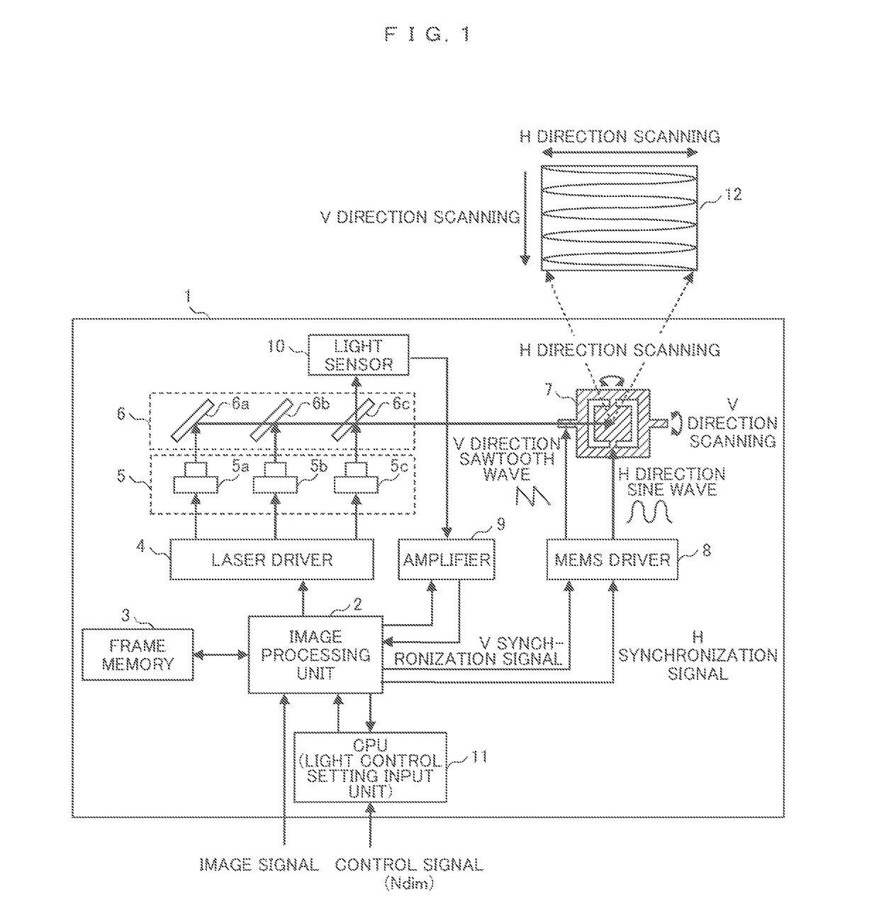
[0031]FIG. 1 is a block diagram illustrating the overall configuration of a laser projection display device according to Example 1. A laser projection display device 1 includes an image processing unit 2, a frame memory 3, a laser driver (a laser light source driving unit) 4, a laser light source 5, a reflection mirror 6, a MEMS scanning mirror 7, a MEMS driver 8, an amplifier 9, a light sensor 10, and a central processing unit (CPU) 11, and displays a display image 12 on a projection surface. The configuration and the operation of each unit will be described.

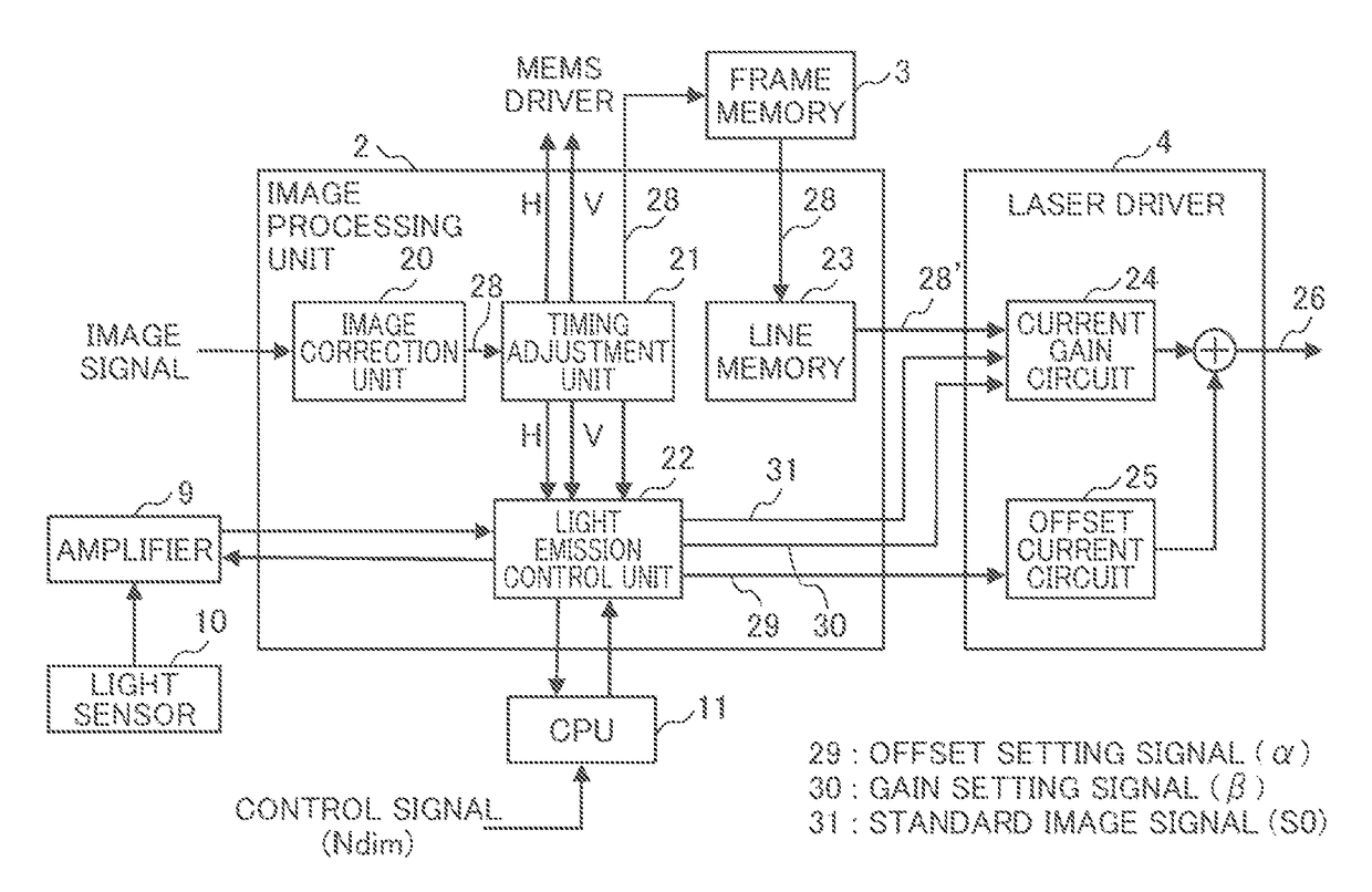
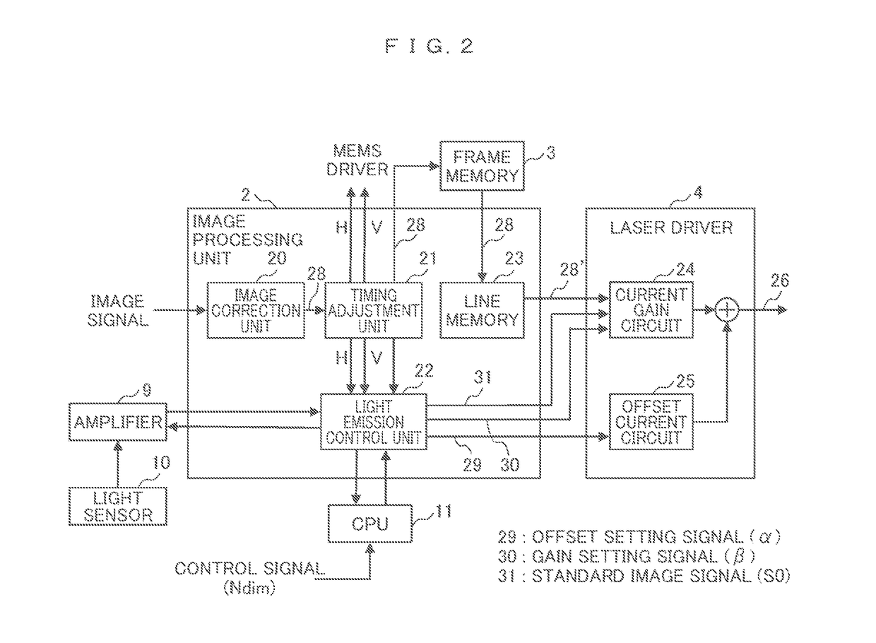
[0032]The image processing unit 2 generates an image signal in which an image signal input from the outside is variously corrected, generates a horizontal synchronization signal (an H synchronization signal) and a vertical synchronization signal (a V synchronization signal) synchronized to the image signal, and supplies the signals to the MEMS driver 8. Here, the horizontal synchronization signal and the vertical synchronizatio...

example 2

[0074]In Example 1, processing of optimizing the current setting with respect to one standard image signal S0 has been described. In contrast, in Example 2, processing of simultaneously optimizing current setting with respect to two standard image signals S1 and S2 will be described. That is, the current setting is performed such that a light amount which is closest to two corresponding light amount target values P1 and P2 set in advance, can be obtained. Accordingly, it is possible to stably display the display image 12 over image signals in a wide range, compared to Example 1.

[0075]Hereinafter, the current setting processing of Example 2 will be described by using FIG. 7 and FIGS. 8(a) and 8(b). Furthermore, a device configuration and a signal processing unit are in common with those of Example 1 (FIG. 1 and FIG. 2), and the detailed description thereof will be omitted.

[0076]FIG. 7 is a diagram illustrating a current setting method according to Example 2 by using the light amount-...

example 3

[0086]In Example 3, a method of suppressing a luminance change and a chromaticity change at the time of performing the light control processing will be described. As with a general display device, the laser projection display device has a light control processing function of adjusting a display luminance in a wide range in order to display an image with a suitable brightness according to the brightness of the use environment. For this reason, the information number dimming (Ndim) determining the brightness of the image is input into the light control setting input unit. Then, the light control mode corresponding to a discrete brightness, and the light control step partitioning the light control mode into a plurality of brightnesses are allocated according to the information Ndim. In each of the light control modes, the Look Up Table (LUT) coincident with the light amount-forward direction current properties of the laser is provided, and a light control amount is read out from the LU...


PUM


Abstract

A laser projection display device 1 includes a laser light source driving unit 4 setting a current which drives a laser light source according to an image signal, a light sensor 10 detecting a light amount of the laser light generated by the laser light source 5, and a light emission control unit 22 emitting light by supplying a standard image signal and a current setting signal to the laser light source driving unit and setting the laser light source driving unit such that the light amount detected by the light sensor becomes a target value. The light emission control unit supplies the current setting signal to the laser light source driving unit such that light emission is performed a plurality of times with a predetermined current difference, in a fly-back period in one frame of the image signal.

Description

CLAIM OF PRIORITY[0001]The present application claims priority from Japanese patent application serial No. JP 2016-061978, filed on Mar. 25, 2016, the content of which is hereby incorporated by reference into this application.BACKGROUND OF THE INVENTION[0002](1) Field of the Invention[0003]The present invention relates to a laser projection display device which performs scanning exiting light from a semiconductor laser or the like with a two-dimensional scanning mirror and performs an image display.[0004](2) Description of the Related Art[0005]Recently, a laser projection display device using a two-dimensional scanning mirror such as a micro electro mechanical systems (MEMS) mirror and a semiconductor laser light source has spread. At this time, technologies as described below have been proposed in order to stabilize the brightness (the luminance) of a video to be display.[0006]For example, in JP 2006-343397 A, a configuration is disclosed in which light emission intensity of laser ...

Claims


Application Information

Patent Timeline
Patent Type & Authority Patents(United States)
IPC IPC(8): H04N9/31
CPCH04N9/3155H04N9/3161H04N9/3135G02B26/105G03B21/2033G03B21/2053H04N9/3194
Inventor OGI, YUYASEO, YOSHIHO
Owner HITACHI-LG DATA STORAGE
Why Eureka
Try Eureka