Multi-power level compact fluorescent lamp assembly

a compact fluorescent and multi-power technology, applied in the field of fluorescent lamps, can solve the problems of insufficient replacement, inconvenient replacement, and none of these bulbs will suffice as 60 watt replacements, and achieve the effect of simplifying the offering and inventory point-of-sale challenges

Inactive Publication Date: 2014-08-21
GENERAL ELECTRIC CO
View PDF4 Cites 0 Cited by
  • Summary
  • Abstract
  • Description
  • Claims
  • Application Information

AI Technical Summary

Benefits of technology

[0008]Given the aforementioned deficiencies, a need exists for an integrated lighting solution that (a) can be set for several lumen or wattage levels of light output before installation and (b) addresses the consumer desire for lighting control and flexibility. A need also exists for a lighting solution that can ...

Problems solved by technology

This can be particularly problematic given the number of different light fixtures in modern homes and the different requirements for light output and lumen requirements associated with these light fixtures.
Additionally, many lighting fixtures are restricted to bulbs of a particular wattage, or to bulbs that do not exceed a particular wattage.
Although the consumer may have a supply of 25 W, 75 W, and 100 W light bulbs, none of these bulbs will suffice as a suitable replacement for the 60 W bulb.
The 25 W bulb is suboptimal for reading, and is therefore an inadequate repla...

Method used


Image

  • Multi-power level compact fluorescent lamp assembly
  • Multi-power level compact fluorescent lamp assembly
  • Multi-power level compact fluorescent lamp assembly

Examples


first embodiment

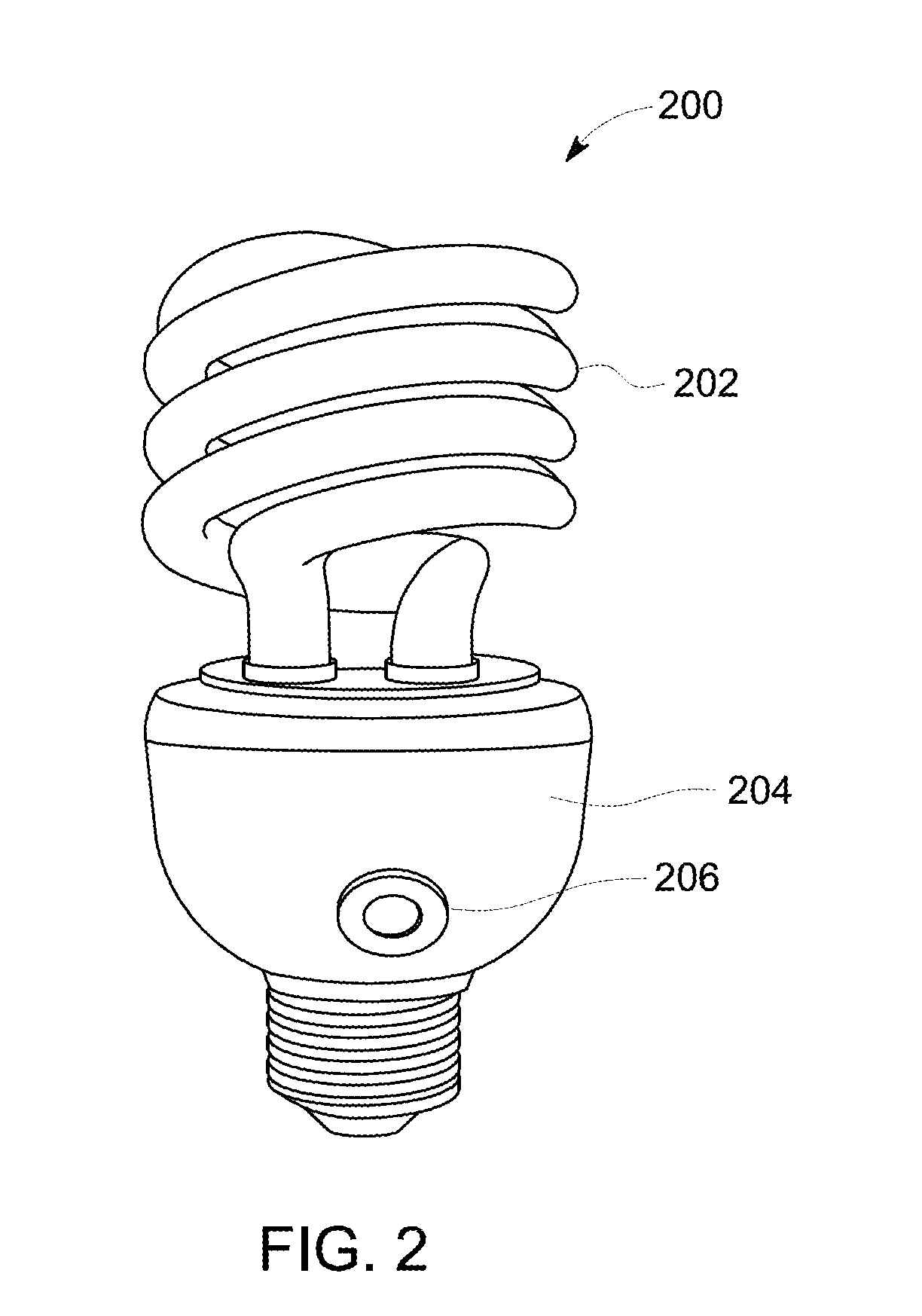
[0020]FIG. 2 is an illustration of a variable lumen CFL constructed in accordance with the present invention.

second embodiment

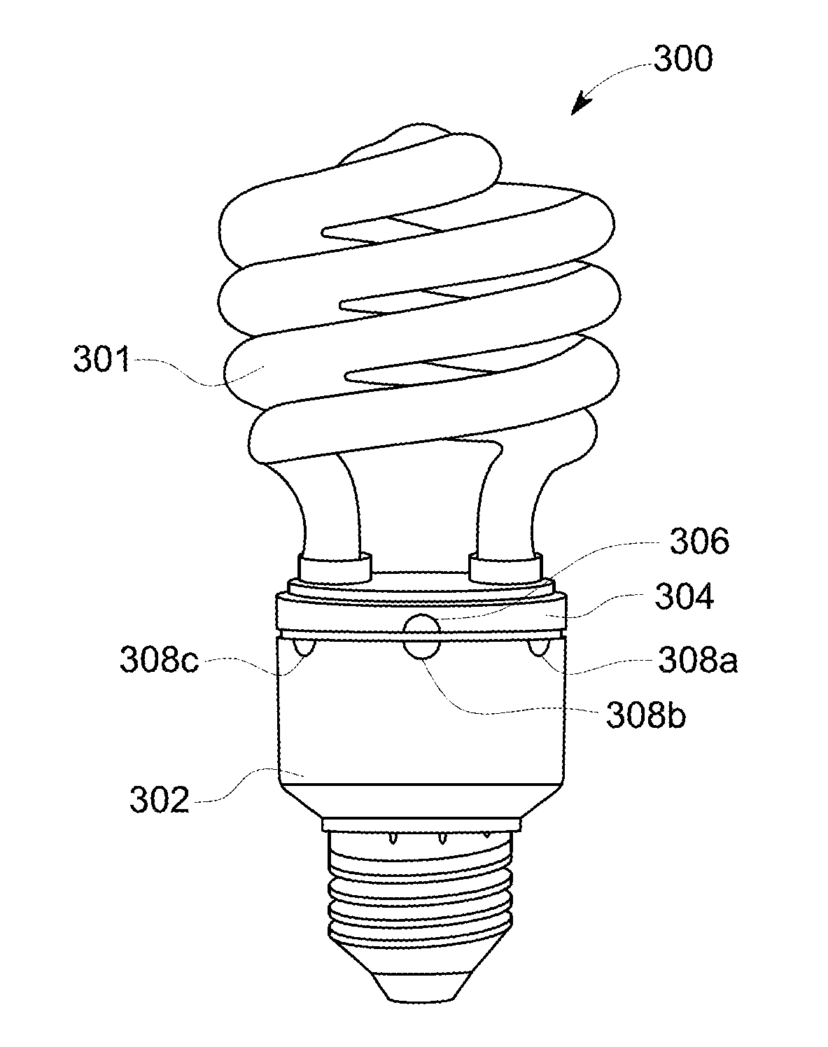
[0021]FIG. 3 is an illustration of a variable lumen CFL constructed in accordance with the present invention.

[0022]FIG. 4 is a more detailed illustration of aspects of the variable lumen CFL illustrated in FIG. 3.

[0023]FIG. 5 is a block diagram illustration of major circuit components of a conventional lighting assembly.

[0024]FIG. 6 is a block diagram illustration of major circuit components of the variable lumen CFL illustrated in FIG. 2.

third embodiment

[0025]FIG. 7 is a block diagram illustration of major circuit components of a variable lumen lamp assembly constructed in accordance with the present invention.

[0026]FIG. 8 is an illustration of a switch configured for use with the variable lumen lamp assembly illustrated in FIG. 7.


PUM


Abstract

Provided is a light assembly including a bulb, a lamp base enclosure having circuitry therein configured to supply power to the bulb, and an integrated and dial electrically coupled to the bulb and the lamp base. The dial is operable for selecting one of a plurality of predetermined power settings for the light assembly prior to installation.

Description

FIELD OF THE INVENTION[0001]The present invention relates generally to fluorescent lamps. More particularly, the present invention relates to controlling the output wattage of compact fluorescent lamps (CFLs).BACKGROUND OF THE INVENTION[0002]Conventional light bulbs provide only one wattage or lumen setting for light output. This can be particularly problematic given the number of different light fixtures in modern homes and the different requirements for light output and lumen requirements associated with these light fixtures. To satisfy these requirements, many consumers maintain an ample supply of different wattage bulbs.[0003]Additionally, many lighting fixtures are restricted to bulbs of a particular wattage, or to bulbs that do not exceed a particular wattage. By way of example, if a consumer has a small table reading lamp that requires a 60 watt (W) incandescent bulb, and the bulb burns out, it must be replaced by another 60 W incandescent bulb. Although the consumer may have...

Claims


Application Information

Patent Timeline
IPC IPC(8): H05B37/02F21V23/04
CPCF21V23/04H05B37/02H05B41/3921H05B41/40H01J61/56H01J61/327Y02B20/00H05B47/10
Inventor GERGELY, JACINTBENKO, NORBERT ZOLTANLUCZ, PETERSZABO, GABORTOTH, LORAND LEHELROLLE, ROLAND
Owner GENERAL ELECTRIC CO
Why Eureka
Try Eureka