Indicator member, indicator unit and indicator instrument

a technology of indicator parts and indicators, applied in the field of indicators, can solve the problems of increased man-hours for assembly, increased manufacturing costs of indicator parts, and increased parts number, and achieve the effects of preventing a dark area, preventing non-uniform brightness, and low cos

Active Publication Date: 2018-06-12
YAZAKI CORP
View PDF18 Cites 3 Cited by
  • Summary
  • Abstract
  • Description
  • Claims
  • Application Information

AI Technical Summary

Benefits of technology

The invention provides a new design for an indicator member that prevents dark areas and non-uniform brightness. The reflection part includes multiple partial reflection parts with different directions of reflection, which disperses the brightness in the pointing direction and the rear end direction. The indicator member also includes a notch that reflects light from the pointing direction reflection face towards the upper face of the pointing part, preventing a dark area from being formed. Additionally, the invention includes a light guide part that guides light from the indicator shaft to the pointing part, reducing light leakage from the base part. These features improve the lighting quality and prevent non-uniform brightness, while reducing the cost of the indicator member.

Problems solved by technology

However, there is a problem that, when the light diffusing component and the filter member and such are provided to prevent the formation of the dark area D at the section R of the upper face 953 of the indicator part 950 located above the hollow reflection part 960 as described above, the number of components is increased and the man-hour for assembling is increased as well, causing an increase in the manufacturing cost of the indicator member.

Method used


Image

  • Indicator member, indicator unit and indicator instrument
  • Indicator member, indicator unit and indicator instrument
  • Indicator member, indicator unit and indicator instrument

Examples


Embodiment Construction

[0261](1.8)

[0262]In the following, a vehicle display device as one embodiment of an indicator instrument according to the present invention is explained in reference to FIGS. 1 through 4B.

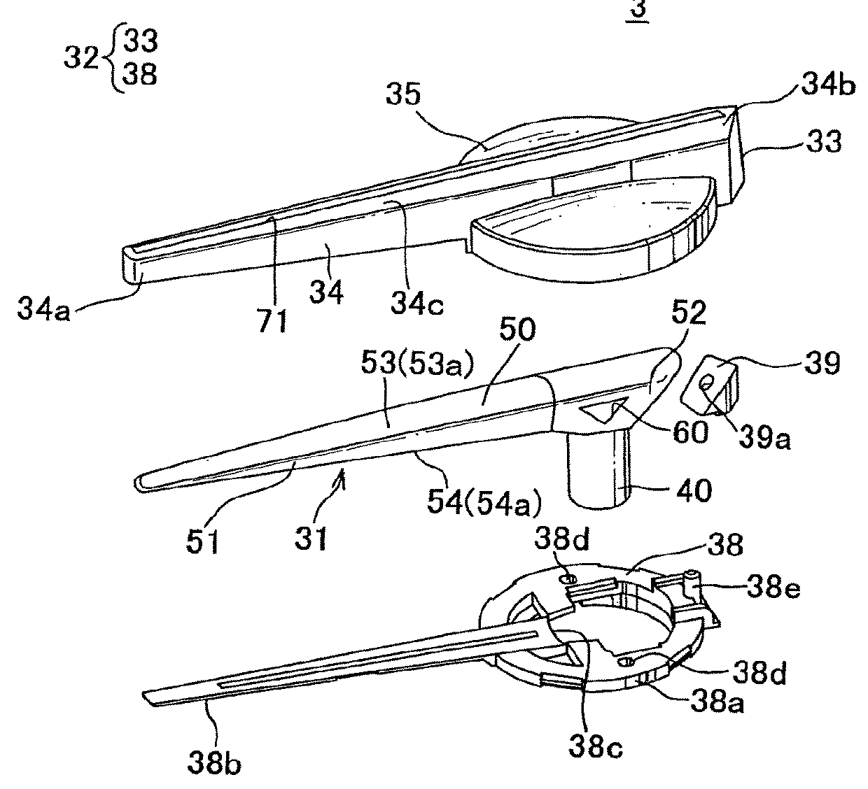
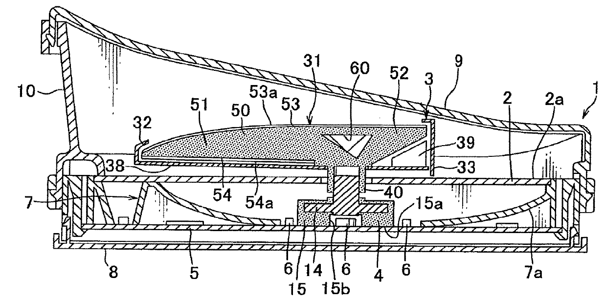
[0263]In FIG. 1, a vehicle display device 1 is a speed meter which displays a vehicle speed, for example. The vehicle display device 1 includes a dial plate 2 having a surface 2a (i.e. a surface which is visible by a viewer) provided with indexes such as scale marks and numbers, letters or symbols, a light-emitting indicator (hereinafter called an indicator) 3 as an indicator unit positioned on the surface 2a of the dial plate 2, a drive device 4 having an indicator shaft 14 including a distal end at which the indicator 3 is attached, a circuit board 5 including a circuit pattern, an electronic component and such and including the drive device 4 fixed to the circuit board 5, a plurality of light sources 6 provided at the circuit board 5, a case 7 having a tapered portion 7a formed from a central po...


PUM


Abstract

To provide an inexpensive indicator member which can prevent a dark area from being formed at a location above a reflection part, an indicator unit having the indicator member and an indicator instrument having the indicator unit. A hollow reflection part provided to an indicator part of an indicator main body of a light-emitting indicator includes a plurality of partial reflection parts having at least an pointing direction reflection face, a rear end direction reflection face and a corner formed at an intersection of the pointing direction reflection face and the rear end direction reflection face and arranged at a location opposed to the base part. The corners of the respective partial reflection parts adjacent to each other are displaced in a pointing direction or in a rear end direction.

Description

[0001]This application is a divisional application of U.S. application Ser. No. 13 / 980,945 filed Jul. 22, 2013 which claims the right of priority under 35 U.S.C. § 119 based on Japanese Patent Application Nos. 2011-015017 filed Jan. 27, 2011; 2011-014246 filed Jan. 26, 2011; JAPAN 2011-014245 filed Jan. 26, 2011 and JAPAN 2011-014244 filed Jan. 26, 2011.TECHNICAL FIELD[0002](1.1), (2.1), (3.1)[0003]The present invention relates to an indicator member made of translucent material which becomes luminous by receiving the light from a light source, an indicator unit having said indicator member and an indicator instrument having said indicator unit.[0004](4.1)[0005]The present invention relates to an indicator member arranged to guide the light from a translucent indicator shaft to be luminous, an indicator unit having said indicator member and an indicator instrument having said indicator unit.BACKGROUND ART[0006](1.2)[0007]In general, a vehicle is mounted with a vehicle display device...

Claims


Application Information

Patent Timeline
Patent Type & Authority Patents(United States)
IPC IPC(8): G01D13/26G01D13/22B60Q3/62B60K35/00F21V8/00F21V7/00F21W111/00
CPCG01D13/22G01D13/265B60K35/00B60Q3/62F21V7/00G02B6/0055B60K2350/2095F21W2111/00B60K2350/203B60K2350/206B60K2360/20B60K2360/27B60K2360/33B60K2360/6992
Inventor MIYAZAWA, TOMOHIROOGAWA, MASAYUKI
Owner YAZAKI CORP
Why Eureka
Try Eureka