Supercharge Your Innovation With Domain-Expert AI Agents!

Circuit for compensation for time variation of temperature in an inductive sensor

a technology of inductive sensor and circuit, applied in the field of sensors, can solve the problems of reducing absolute accuracy, limiting the overall absolute accuracy of inductive transducers, and variable output of sensors, and achieve the effect of accurate data

Inactive Publication Date: 2011-02-22
LORD CORP
View PDF11 Cites 0 Cited by
  • Summary
  • Abstract
  • Description
  • Claims
  • Application Information

AI Technical Summary

Benefits of technology

This solution provides highly accurate displacement sensing independent of temperature changes, reducing errors and improving the accuracy of both single and dual coil transducers, with the ability to maintain precision across a wide temperature range.

Problems solved by technology

Temperature changes can effect components within a sensor, and one challenge has been that sensor output has varied with temperature of sensor components.
The effect of temperature on inductive transducers limits their overall absolute accuracy.
However, if one coil experiences a different temperature environment than the other coil, a signal proportional to the temperature gradient between the two coils will appear at the circuit output, significantly reducing absolute accuracy.
The '593 patent recognizes that a temperature gradient across the coils can provide a change in the resistance of the wire forming one of the coils more than it changes the resistance in the other coil, and this difference in resistance can change the differential impedance of the coils, essentially mimicking a change in position, resulting in an error in measured displacement.

Method used


Image

  • Circuit for compensation for time variation of temperature in an inductive sensor
  • Circuit for compensation for time variation of temperature in an inductive sensor
  • Circuit for compensation for time variation of temperature in an inductive sensor

Examples


Embodiment Construction

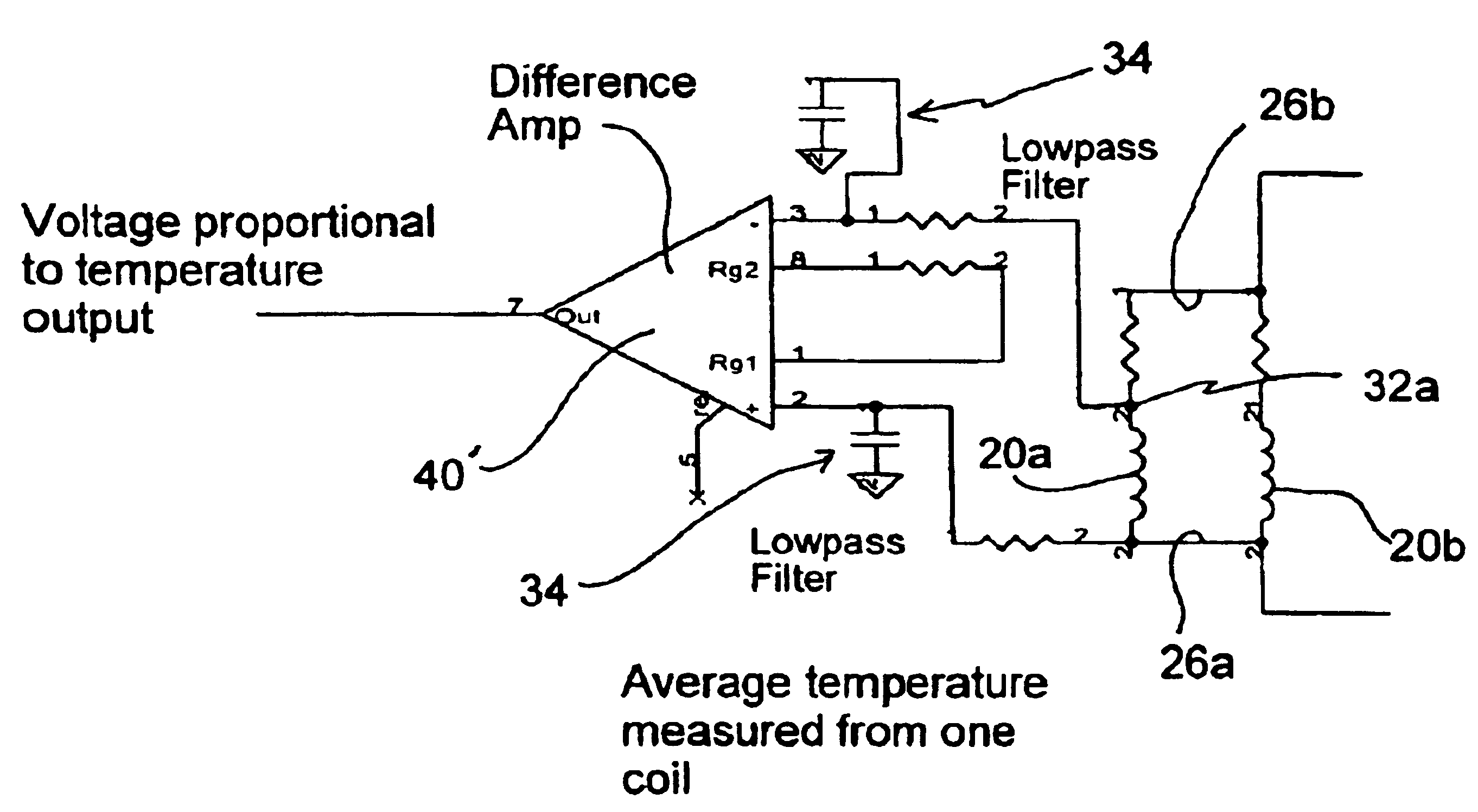
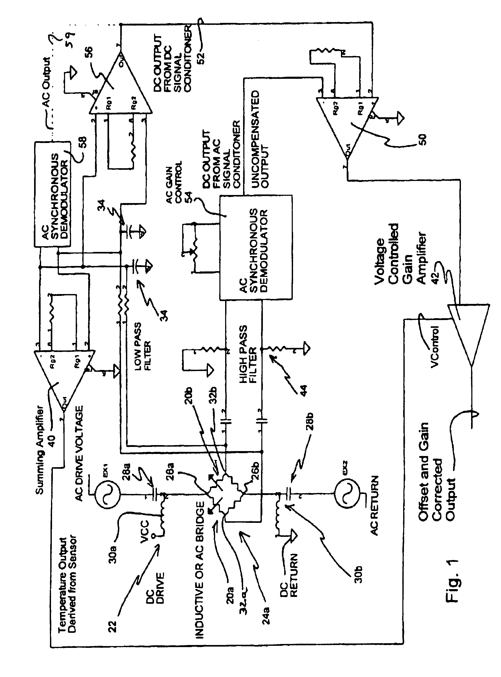
[0026]The present inventors recognized that a DVRT sensor that includes the circuit of '593 patent, incorporated herein by reference, provides substantial advantage in temperature compensation, but does not include all the temperature correcting needed. They recognized that a bridge circuit, such as that included in a DVRT, cancels the effects of uniform changes in temperature in the wiring of the coils of the DVRT, a substantial advantage for such differential sensors. They also recognized that the circuit of the '593 patent adequately corrects for the different coil wire resistances introduced by temperature gradients across the coils, an advantage in applications, such as automotive where such temperature gradients are common. The inventors then recognized an additional mechanism by which a change in temperature can cause errors: the magnetic permeability of the ferrite core varies with temperature. This change in permeability with temperature introduces a change in the inductanc...


PUM


Abstract

A sensing device includes a circuit that compensates for time and spatial changes in temperature. The circuit includes elements to correct for variation in permeability of a highly permeable core of a differential variable reluctance transducer as temperature changes. The circuit also provides correction for temperature gradients across coils of the transducer.

Description

RELATED APPLICATION[0001]This application is a continuation-in-part of Provisional U.S. Patent Application 60 / 220,364, filed Jul. 24, 2000.FIELD OF THE INVENTION[0002]This invention generally relates to sensors. More particularly, it relates to variable reluctance transducers. Even more particularly, it relates to an improved system for greater accuracy in determining position or displacement in view of changes in temperature.BACKGROUND OF THE INVENTION[0003]Sensors are being developed for use in roads, bridges, dams, buildings, towers, and vehicles that may provide many information, including displacement, strain, speed, acceleration, temperature, pressure, and force.[0004]Temperature changes can effect components within a sensor, and one challenge has been that sensor output has varied with temperature of sensor components. The effect of temperature on inductive transducers limits their overall absolute accuracy. To reduce the temperature effect, inductive transducers, such as a d...

Claims


Application Information

Patent Timeline
Patent Type & Authority Patents(United States)
IPC IPC(8): G01B7/14G01D3/036G01D5/20
CPCG01D5/2013G01D3/036
Inventor TOWNSEND, CHRISTOPHER P.ARMS, STEVEN W.
Owner LORD CORP
Features
  • R&D
  • Intellectual Property
  • Life Sciences
  • Materials
  • Tech Scout
  • Unparalleled Data Quality
  • Higher Quality Content
  • 60% Fewer Hallucinations
Learn More