
Stirring blade structure of sludge drier
A sludge drying and stirring paddle technology, which is applied in the direction of dewatering/drying/concentrating sludge treatment, etc., can solve the problems of endangering the normal operation of the system, increasing the driving load of the hollow hot shaft, and reducing the space of the sludge slurry channel, etc. It is not easy to damage the machine, it is not easy to accidentally get stuck, and the heat exchange efficiency is increased.
Patent Information
- Authority / Receiving Office
- CN · China
- Patent Type
- Applications(China)
- Current Assignee / Owner
- Publication Date
- 2016-12-14
Smart Images
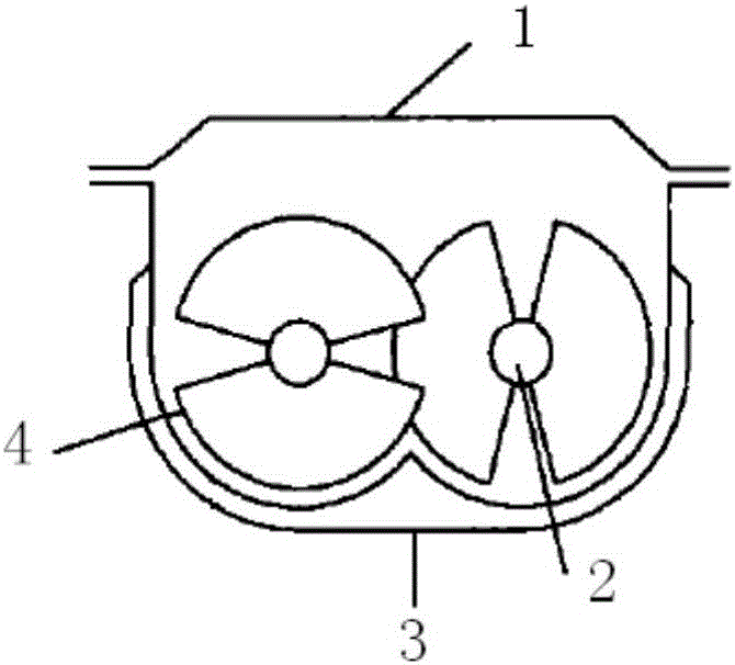
Figure 1 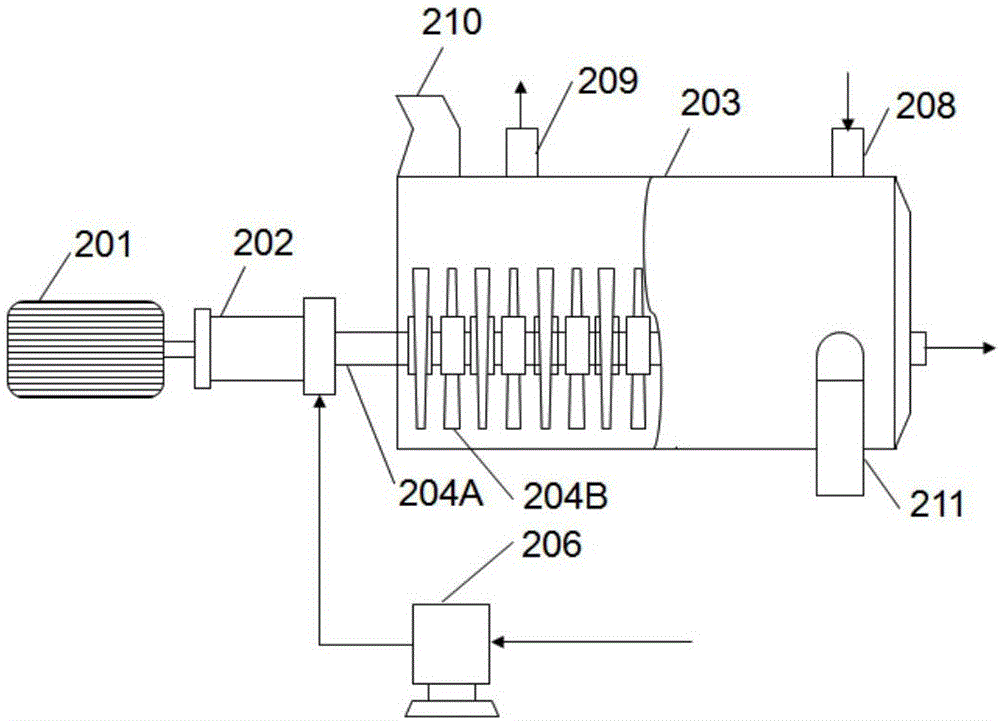
Figure 2 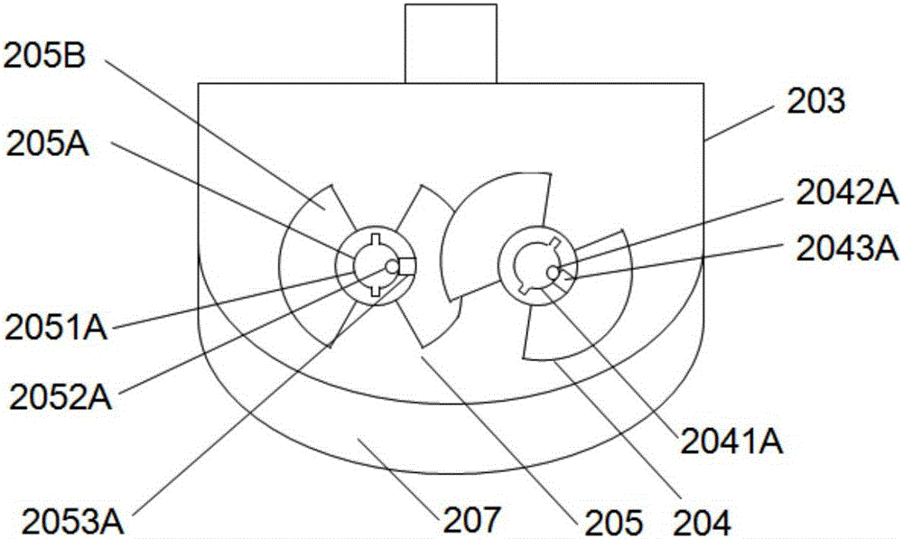
Figure 3
Abstract
Description
technical field
[0001] The invention relates to the technical field of sludge treatment, in particular to a stirring paddle structure applied to a sludge dryer. Background technique
[0002] Sludge is an important pollution output formed in industrial and agricultural production and urban life. will produce sludge. Sludge contains a large number of harmful microorganisms, heavy metals and organic pollutants. If not properly disposed of, it will have a serious negative impact on the natural environment and people's health.
[0003] Sludge incineration is to make the combustible substances in sludge burn at high temperature and make them oxidatively decompose, so as to achieve the purpose of reducing sludge capacity, killing harmful microorganisms, removing toxicity and making full use of energy. Sludge incineration is a widely used and mature sludge high-temperature treatment technology in foreign countries. It can minimize the volume of sludge, and has the advantages of fa...
Examples
Embodiment Construction
[0027] The technical solutions of the present invention will be further specifically described below through examples.
[0028] first preferred embodiment
[0029] The stirring paddle structure provided by the invention is applied to a hollow paddle sludge dryer. Figure 2A-2BA hollow paddle sludge dryer equipped with the stirring paddle structure is shown. The drying machine includes a drive motor 201, a biaxial transmission box 202, a heat exchange chamber 203, a first hollow paddle 204, a second hollow paddle 205, a heat medium delivery pump 206, a heat conduction jacket 207, an air inlet 208, and a steam outlet 209, material inlet 210 and material outlet 211. The drive motor 201 is used to provide driving force for the rotation of the first hollow paddle 204 and the second hollow paddle 205 around its hollow paddle shaft; the double shaft transmission box 202 is connected to the motor shaft of the drive motor 201 and has two torque output shafts, two The two torque outp...