
Municipal garden landscaping soil environment-friendly repairing treatment device
A landscaping and treatment device technology, applied in the field of landscaping, can solve the problems of poor treatment effect, complex structure, unreasonable design, etc., and achieve the effect of improving quality, good mixing uniformity, and improving mixing uniformity
Patent Information
- Authority / Receiving Office
- CN · China
- Current Assignee / Owner
- Publication Date
- 2017-07-28
- Estimated Expiration
- Not applicable · inactive patent
Smart Images
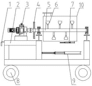
Figure 1 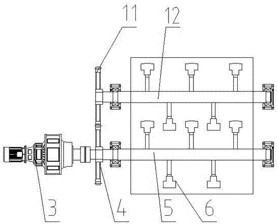
Figure 2 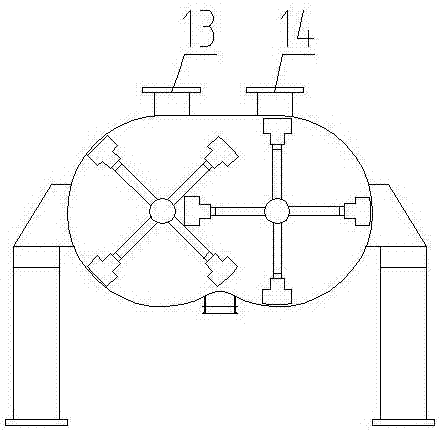
Figure 3
Abstract
Description
technical field
[0001] The invention belongs to the technical field of landscaping, and in particular relates to a municipal landscaping soil environmental protection restoration treatment device. Background technique
[0002] Municipal garden refers to the beautiful natural environment created by using engineering technology and artistic means in a certain area by transforming the terrain (or further building mountains, stacking stones, water management), planting trees and flowers, building buildings and arranging garden roads. and recreational areas. Due to soil pollution caused by human production activities, pollutants mainly include: solid waste, organic matter, heavy metals, etc. These pollutants will adversely affect the growth of flowers, trees and other plants used in landscaping. Therefore, there is an urgent need to restore the polluted soil, and the existing municipal landscaping soil environmental protection restoration treatment device has the disadvantages o...
Examples
Embodiment Construction
[0013] In order to facilitate those skilled in the art to understand the technical solution of the present invention, the technical solution of the present invention will be further described in conjunction with the accompanying drawings.
[0014] Such as figure 1 , figure 2 , image 3 As shown, a municipal landscaping soil environmental protection restoration treatment device includes: driving gear 4, driving shaft 5, paddle 6, stirring box 10, driven gear 11, driven shaft 12, characterized in that: the driving The front end of the shaft 5 is connected to the main shaft of the reduction motor 3 through a coupling. The front part of the driving shaft 5 is provided with a driving gear 4, and the driving gear 4 is meshed with the driven gear 11. When the reduction motor 3 rotates, the driving shaft 5 Rotate in the opposite direction with the driven shaft 12, the driven gear 11 is installed on the front end of the driven shaft 12, the driven shaft 12 and the driving shaft 5 ar...