
Manufacture of fine particles and nano particles and coating thereof
Patent Information
- Authority / Receiving Office
- US · United States
- Current Assignee / Owner
- Publication Date
- 2007-05-31
- Estimated Expiration
- Not applicable · inactive patent
Smart Images
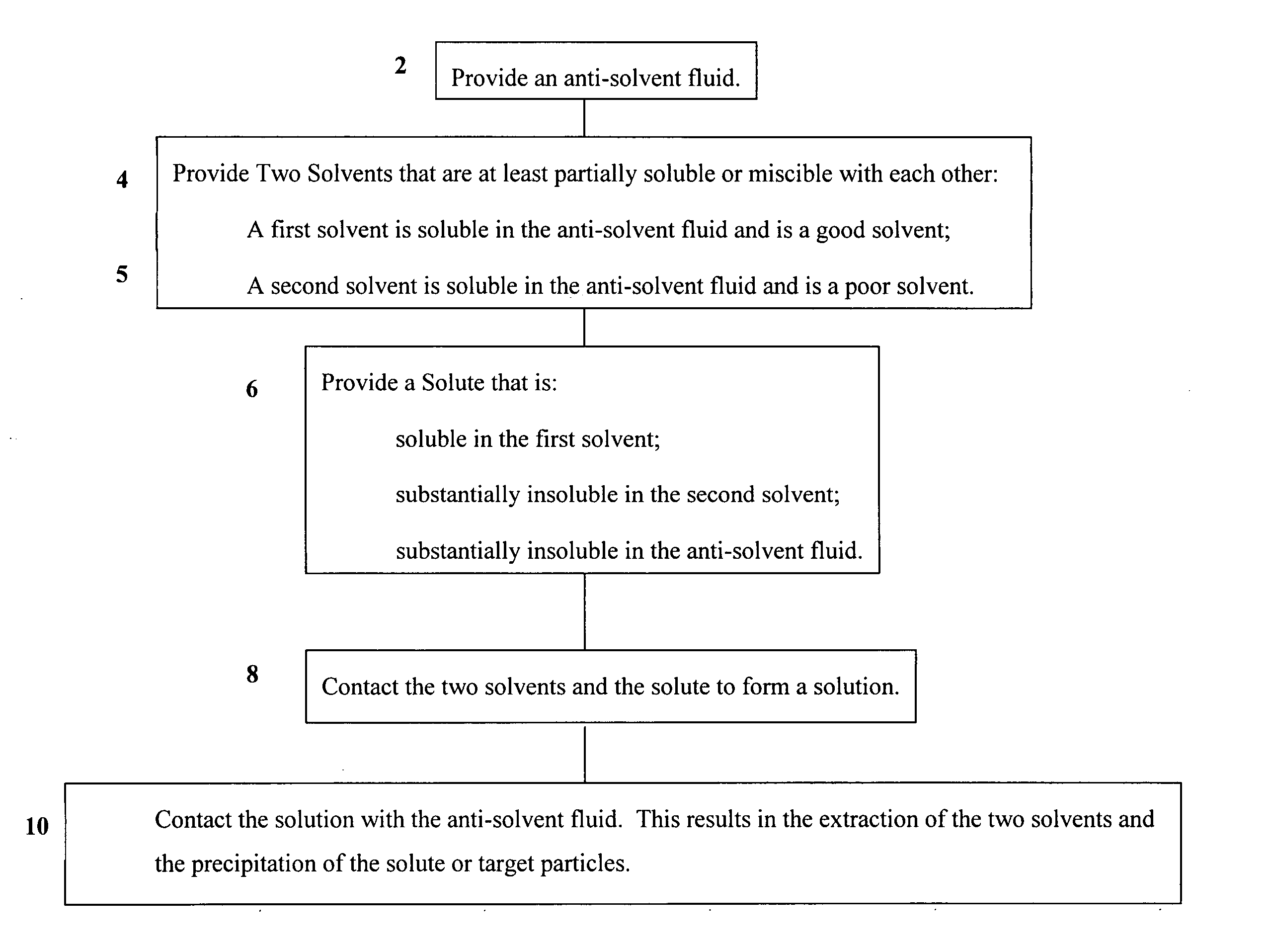
Figure 1 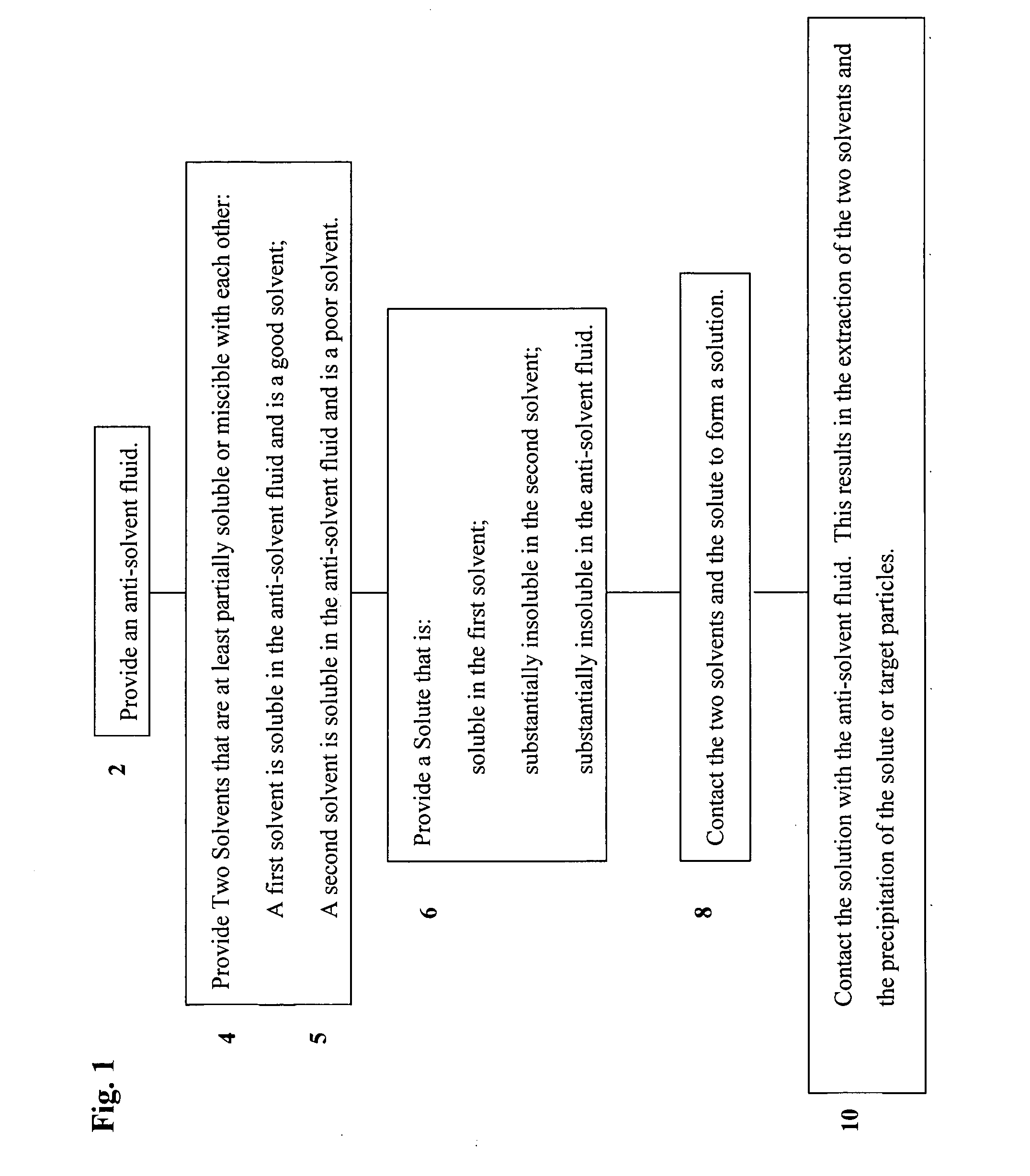
Figure 2 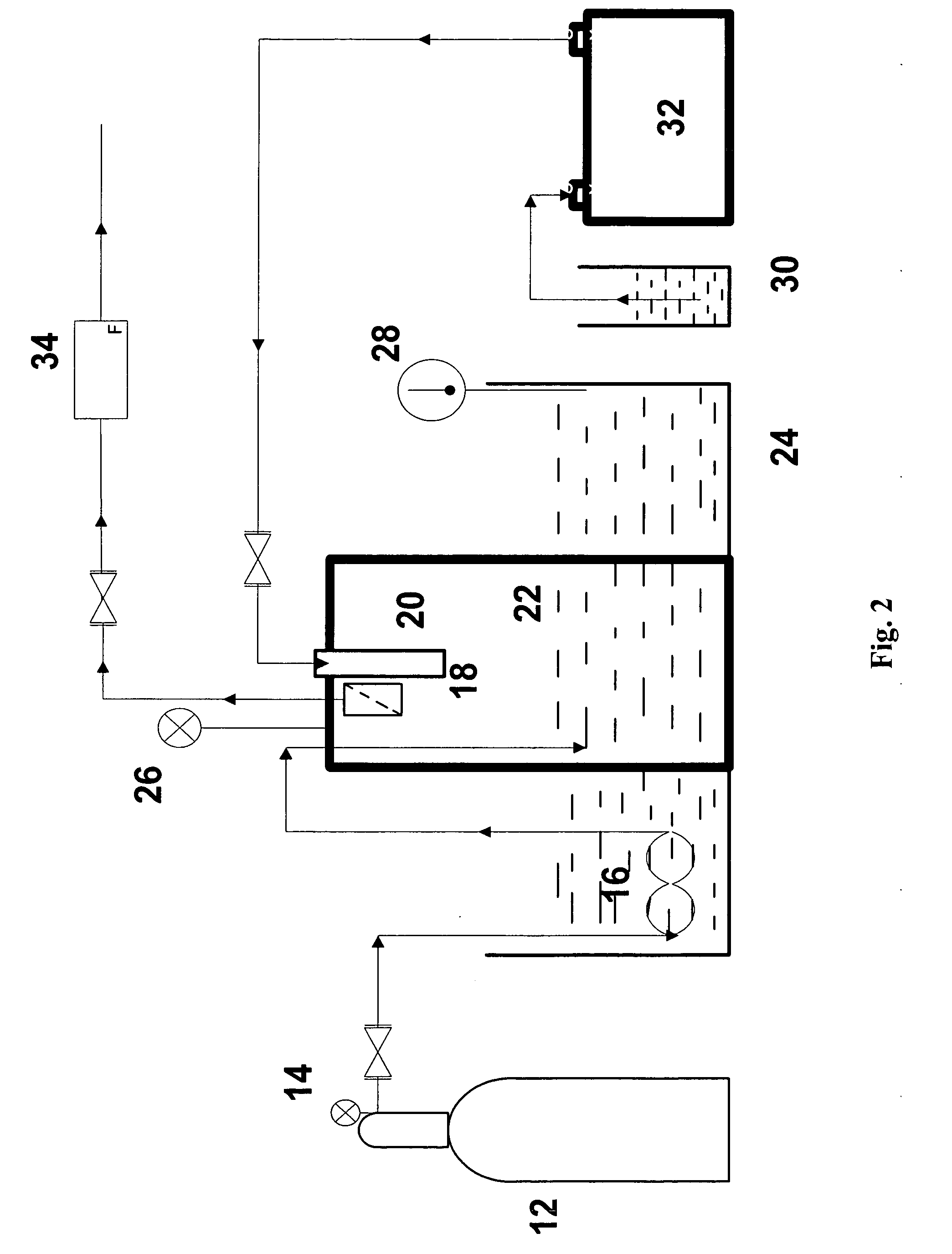
Figure 3
Abstract
Description
CROSS REFERENCE TO RELATED APPLICATION(S)
[0001] The present application claims the benefit of a co-pending provisional patent application entitled “Method For Manufacturing Fine and Nano Particles and Coating Thereof,” which was filed on Nov. 8, 2005 and assigned Ser. No. 60 / 734,573. The entire contents of the foregoing provisional patent application are incorporated herein by reference.BACKGROUND
[0002] 1. Technical Field
[0003] The present disclosure relates to systems and methods for production, formation, and / or manufacturing of micron, submicron and / or nano sized particles as well as particle coating utilizing anti-solvent fluids.
[0004] 2. Background Art
[0005] Processing small particles is important for many fields of study and manufacture including but not limited to pharmaceutics, nutraceutics, food processing paint and copying technologies. Smaller particles sizes can lead to the development of new products as well as more effective products. New techniques for generating...
Examples
example 1
[0065] Experiments are conducted on solutions of high-molecular weight polyvinylpyrrolidone (PVP), Mw=1,300,000, in a binary mixture of good solvent, dichloromethane (DCM) (HPLC Grade, 99.7+%), and poor solvent, acetone (HPLC Grade, 99.5+%), in a high pressure carbon dioxide (CO2) cylinder (Bone Dry, 99.9% pure). The PVP solubility in a binary mixture of DCM and acetone at normal pressure is measured using a laser scattering on a Coulter N4 Plus, for example.
[0066] Experimental setup is illustrated in FIG. 2. An exemplary high-pressure chamber 22 has double-sided (front and back) sapphire windows (320 mm×16 mm) for flow visualization. An exemplary visualization system (not shown) includes a microscope lens, a high-speed CCD camera, a computer with image capture software, and a Nd:YAG dual cavity pulsed laser that produces double shots with an exposure time from 5 μs to 15 μs delay. Polymer solution is injected into a compressed chamber 22 through a micro-nozzle 20 following a 15-mi...
example 2
[0070] The SAS coating process is similar to the SAS particle formation process and can be performed near critical pressure and temperature. Polymethylmethacrylate (PMMA) polymer is dissolved in an organic solvent or combination of solvents and host particles (silica particles) are suspended in the solution. This solution is then sprayed into supercritical CO2. An experimental setup used for coating work is similar to the setup illustrated in FIG. 14. A capillary tube is replaced by a coaxial ultrasonic nozzle to spray the suspension solution. The suspension solution is fed into a high pressure chamber through the central capillary of the ultrasonic nozzle and CO2 is fed through the outer capillary. CO2 flows continuously before start of the suspension injection and continues to flow 2 hours after the injection is stopped.
[0071] An exemplary ultrasonic nozzle is shown in FIG. 6. It comprises two coaxial nozzles. The smaller inner nozzle has an inner diameter of 300 μm with the wall...
example 3
[0083] A setup shown schematically in FIG. 14 is used for the visualization of the breakup patterns of liquids injected into supercritical CO2. The visualization system includes a microscope zoom lens, a high-speed CCD camera, a computer with image capture software and a Nd:YAG dual cavity pulsed laser. To produce a larger amount of PVP particles for analysis, the view cell in this apparatus is replaced with a 910-mL high-pressure chamber placed inside a water bath. Fused silica capillaries of 10-μm, 20-μm, 40-μm, and 127-μm were used as micro-nozzles in experiments on the particle formation. The operational temperature is maintained at 35° C. while the operational pressure varies from 79 to 120 bar.
[0084] The breakup of liquids injected into supercritical CO2 appears to be similar to that observed for the injection of a liquid into an immiscible liquid as shown in FIG. 15. For low flow rates, drops are formed individually at the tip of the nozzle and break off when they attain a p...