
Hybrid vehicle and method of controlling the same
a hybrid vehicle and vehicle technology, applied in the field of hybrid vehicles, can solve the problems of increasing fuel consumption and aforementioned problems, and achieve the effect of avoiding increased fuel consumption
Patent Information
- Authority / Receiving Office
- US · United States
- Current Assignee / Owner
- Publication Date
- 2010-07-22
Smart Images
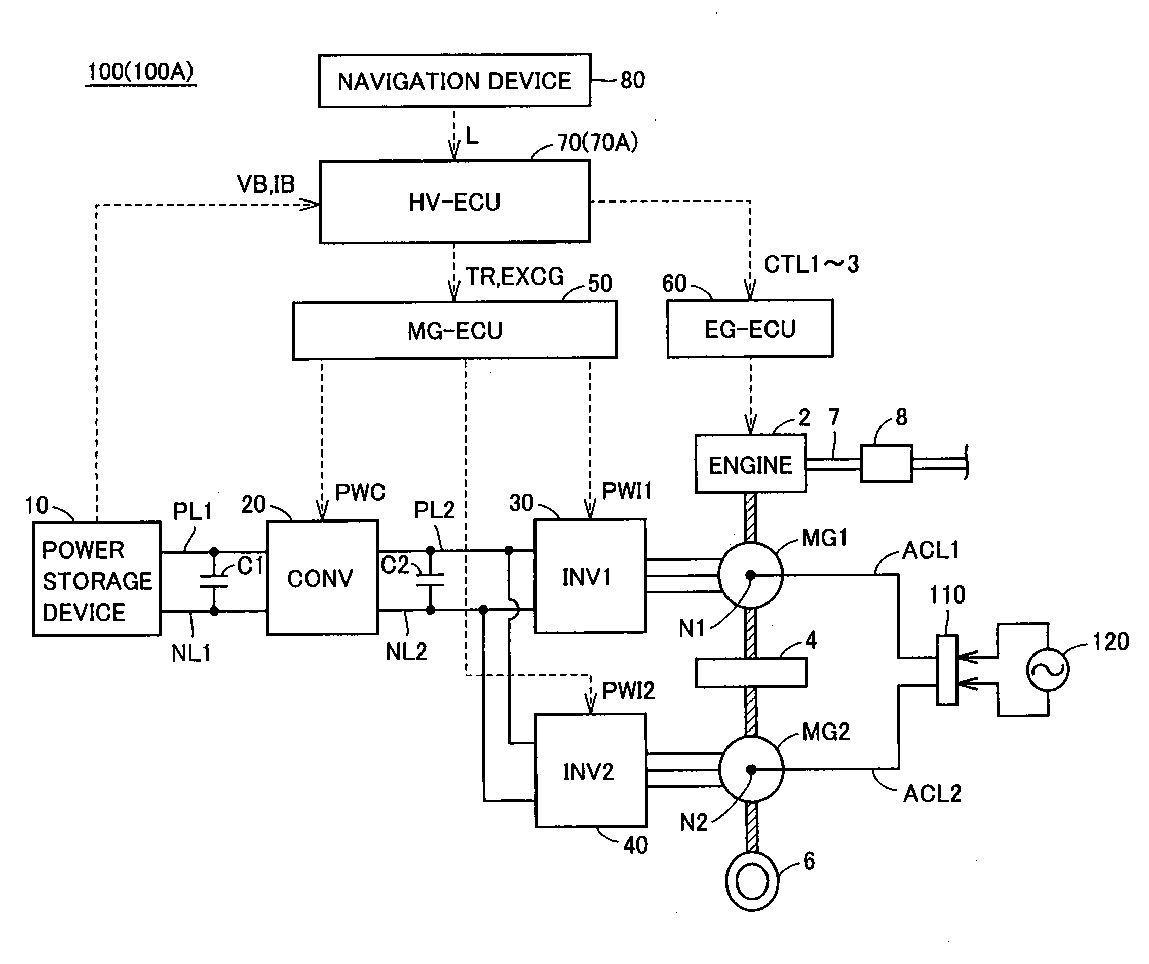
Figure 1 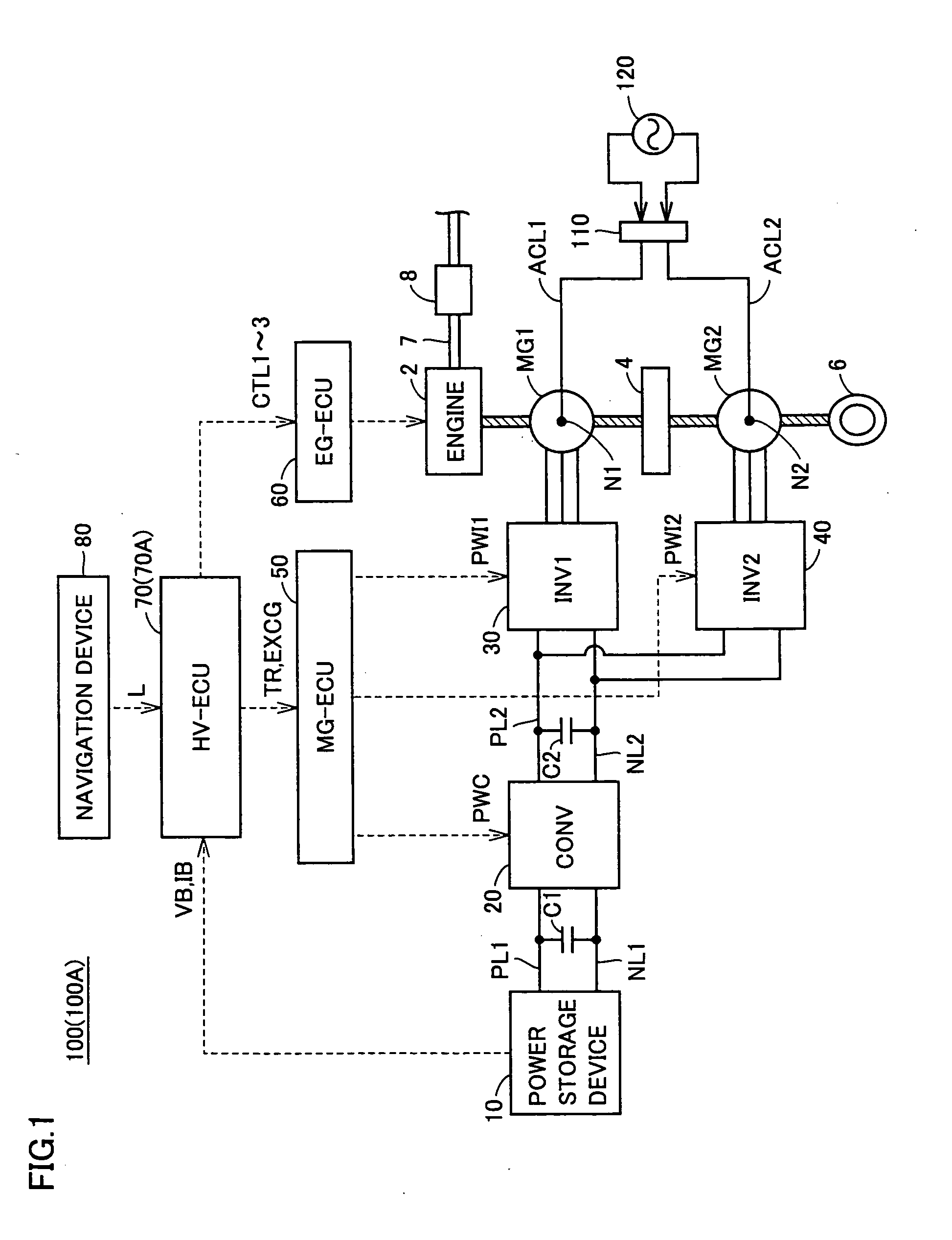
Figure 2 
Figure 3
Abstract
Description
TECHNICAL FIELD
[0001] The present invention relates to a hybrid vehicle equipped with an internal combustion engine and an electric motor as a power source for driving the vehicle, and also relates to a method of controlling the same.BACKGROUND ART
[0002] Hybrid vehicles are receiving attention as environmentally friendly vehicles. A hybrid vehicle is equipped with, not only a conventional engine, but also a power storage device, an inverter and a motor driven by the inverter, as power sources for driving the vehicle.
[0003] Similarly to conventional vehicles having the engine as the only power source, a hybrid vehicle, also equipped with the engine, generally has mounted thereon a catalytic converter for purifying the exhaust gas discharged from the engine.
[0004] Japanese Patent Laying-Open No. 2003-269208 discloses a control apparatus for a hybrid vehicle equipped with a catalytic converter. When the SOC (State of Charge) of a battery drops to its lower limit or below, the control appar...
Examples
first embodiment
[0035]FIG. 1 is an overall block diagram of a hybrid vehicle according to a first embodiment of the present invention. Referring to FIG. 1, a hybrid vehicle 100 includes an engine 2, an exhaust pipe 7, a catalytic converter 8, motor generators MG1 and MG2, a power split mechanism 4 and a wheel 6. Hybrid vehicle 100 also includes a power storage device 10, a boost converter 20, inverters 30 and 40, positive electrode lines PL1 and PL2, negative electrode lines NL1 and NL2, capacitors C1 and C2, electric power lines ACL1 and ACL2, and a connector 110. Hybrid vehicle 100 further includes an MG-ECU (Electric Control Unit) 50, an EG-ECU 60, an HV-ECU 70 and a navigation device 80.
[0036]This hybrid vehicle 100 runs with engine 2 and motor generator MG2 as power sources. Power split mechanism 4 is coupled to engine 2 and motor generators MG1, MG2 to distribute motive power among them. For example, as power split mechanism 4, a planetary gear mechanism having three rotation shafts of a sun ...
second embodiment
[0078]In a second embodiment, when the possible EV-running distance estimated based on the SOC of power storage device 10 is not longer than set traveling distance L, the SOC in which engine 2 is started (hereinafter also referred to as “engine start SOC”) is set at a value larger than in the case where the possible EV-running distance is longer than traveling distance L. This ensures necessary power for traveling during catalyst warm-up after the engine is started.
[0079]The overall configuration of a hybrid vehicle 100A according to the second embodiment is identical to that of hybrid vehicle 100 shown in FIG. 1 according to the first embodiment.
[0080]FIG. 6 is a functional block diagram of an HV-ECU 70A according to the second embodiment. Referring to FIG. 6, HV-ECU 70A further includes an engine-start-SOC setting unit 260 in addition to the configuration of HV-ECU 70 shown in FIG. 2 according to the first embodiment.
[0081]Engine-start-SOC setting unit 260 sets the above-mentioned...