
Heat-treatment tray member and heat-treatment stacked structure
Patent Information
- Authority / Receiving Office
- US · United States
- Current Assignee / Owner
- Publication Date
- 2021-06-10
Smart Images
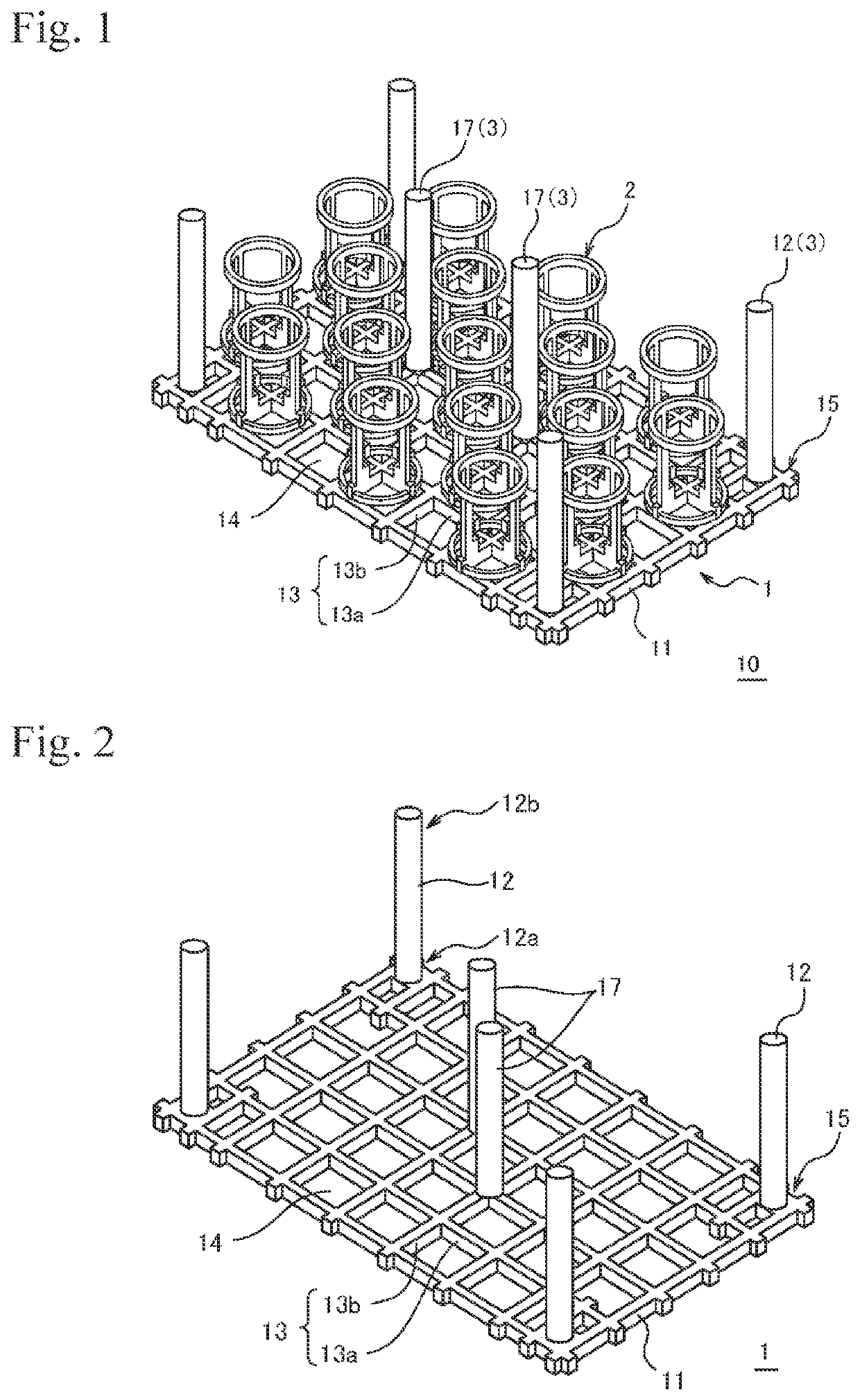
Figure 1 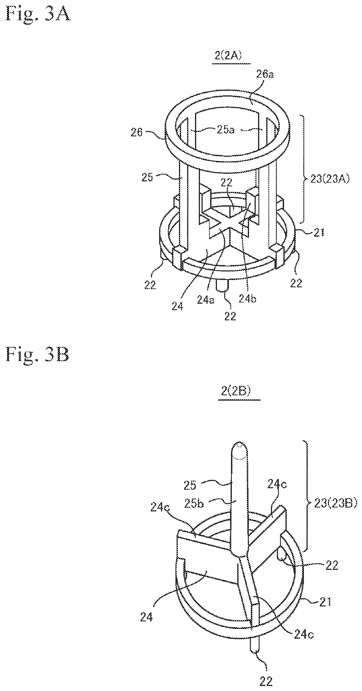
Figure 2 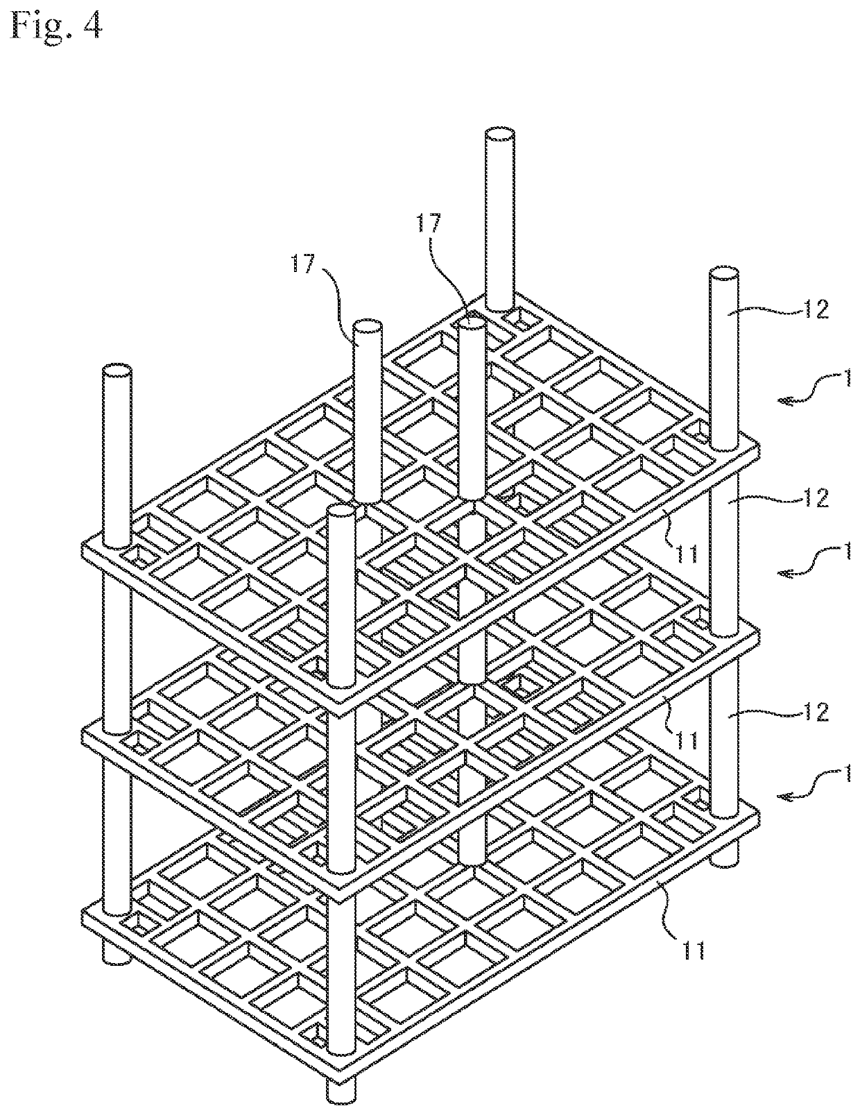
Figure 3
Abstract
Description
FIELD OF THE INVENTION
[0001] The present invention relates to a heat-treatment tray member and a heat-treatment stacked structure. More specifically, the present invention relates to a heat-treatment tray member that, even when repeatedly loaded into a heat treating furnace with parts placed thereon in order to heat-treat the parts, suppresses the occurrence of deforming and cracking, allowing use for an extended period of time, and a heat-treatment stacked structure obtained by stacking the same.BACKGROUND ART
[0002] Carburizing treatment is known as a surface hardening treatment for metal parts. Carburizing treatment is a treatment in which carbon monoxide (CO) gas generated from a carburizing agent and a steel material are brought into contact at a high temperature, thereby introducing and diffusing the carbon into the metal parts to form a surface layer (carburized layer). In particular, for metal parts composed of a low carbon steel or the like having a low carbon content, only th...
Examples
first embodiment
[Heat-Treatment Tray Member of First Embodiment]
[0045]A heat-treatment tray member 10 in a first embodiment, as illustrated in FIG. 1 to FIG. 4, is a composite member (also referred to as a hybrid member) constituted by a tray 1 and a plurality of part receivers 2 detachably mounted onto the tray 1, and is a member repeatedly loaded into a heat treating furnace along with parts to be heat-treated. Then, the tray 1 includes a base part 11 provided with a plurality of mounting parts 13 capable of mounting the part receivers 2 in predetermined positions, the base part 11 is constituted by a carbon composite material, and the part receivers 2 are constituted by a steel material or a nickel (Ni) alloy material.
[0046]In this heat-treatment tray member 10, (a) the tray 1 is a member separate from and not a structure integral with the part receivers 2 as in the conventional example illustrated in FIG. 22, making it possible to simplify the structure of the base part 11. Furthermore, this ma...
second embodiment
[Heat-Treatment Tray Member of Second Embodiment]
[0088]The heat-treatment tray member 10 in a second embodiment, as illustrated in FIGS. 15A and 15B, FIGS. 16A and 16B, and FIG. 17 to FIG. 19, differs from the heat-treatment tray member in the first embodiment that uses the support column 3 and the coupling members 31, 41 as coupling means in that the part receiver 2 and the tray 1 are combined to form tray members 10A, 10B. In the heat-treatment tray member 10 in the second embodiment, the tray members 10A, 10B are stacked in multiple stages to form heat-treatment stacked structures 60A, 60B illustrated in FIG. 14 and FIG. 19. With the heat-treatment stacked structures 60A, 60B, by layering the tray members 10A in multiple stages, it is possible to stack the trays 1, on which a large number of parts to be heat-treated can be placed, in a plurality of stages. It should be noted that, in the following, a coupling means for combining the part receiver 2 and the tray 1 will be describe...
third embodiment
[Heat-Treatment Stacked Structure of Third Embodiment]
[0115]The heat-treatment stacked structure in a third embodiment is a heat-treatment stacked structure obtained by stacking a plurality of the heat-treatment tray members in each embodiment described above, and is repeatedly loaded into a heat treating furnace along with parts to be heat-treated. Then, a heat-treatment tray member 10C in the first stage, as illustrated in FIG. 21, includes the base part 111, the corner support column 112, the center support column 129, and a plurality of part receivers, the corner support column 112 and the center support column 129 being integrally constituted with the base part 111 by a steel material or a Ni alloy material, and the part receivers being detachably mounted onto the base part 111. While not illustrated in FIG. 21, the detachable part receiver is actually selected from the part receivers 2A to 2E mentioned above. As the heat-treatment tray members in the second and subsequent stag...