Antenna

An antenna and transmission line technology, which is applied in the field of antenna and radio frequency, can solve the problems of complex process, great influence of electromagnetic compatibility, exciting surface waves, etc., and achieve the effect of reliable physical connection, omnidirectionality and increased gain

Inactive Publication Date: 2007-08-22
张革军
View PDF0 Cites 4 Cited by
  • Summary
  • Abstract
  • Description
  • Claims
  • Application Information

AI Technical Summary

Problems solved by technology

[0005] But this kind of microstrip patch antenna has the following disadvantages: (1) The frequency band is narrow, and the relative bandwidth is generally 1% to 10%; (2) It will excite the surface (3) The size is too large; (4) There are limitations in the direction, the maximum radiation direction is the vertical patch direction, which makes the physical connection of the antenna more cumbersome in terms of certain use direction requirements
[0007] This microstrip linear antenna also has the following disadvantages: (1) The frequency band is narrow, generally 0.5% to 6% of the relative bandwidth; (2) The gain is small, usually not Greater than 0dBi
[0009] But this kind of antenna has the following disadvantages: (1) narrow bandwidth, generally only 0.1% to 5.5% relative bandwidth; (2) high cost; (3) process Complex; (4) Electromagnetic compatibility has a great influence and is difficult to realize

Method used


Image

  • Antenna
  • Antenna
  • Antenna

Examples


Embodiment Construction

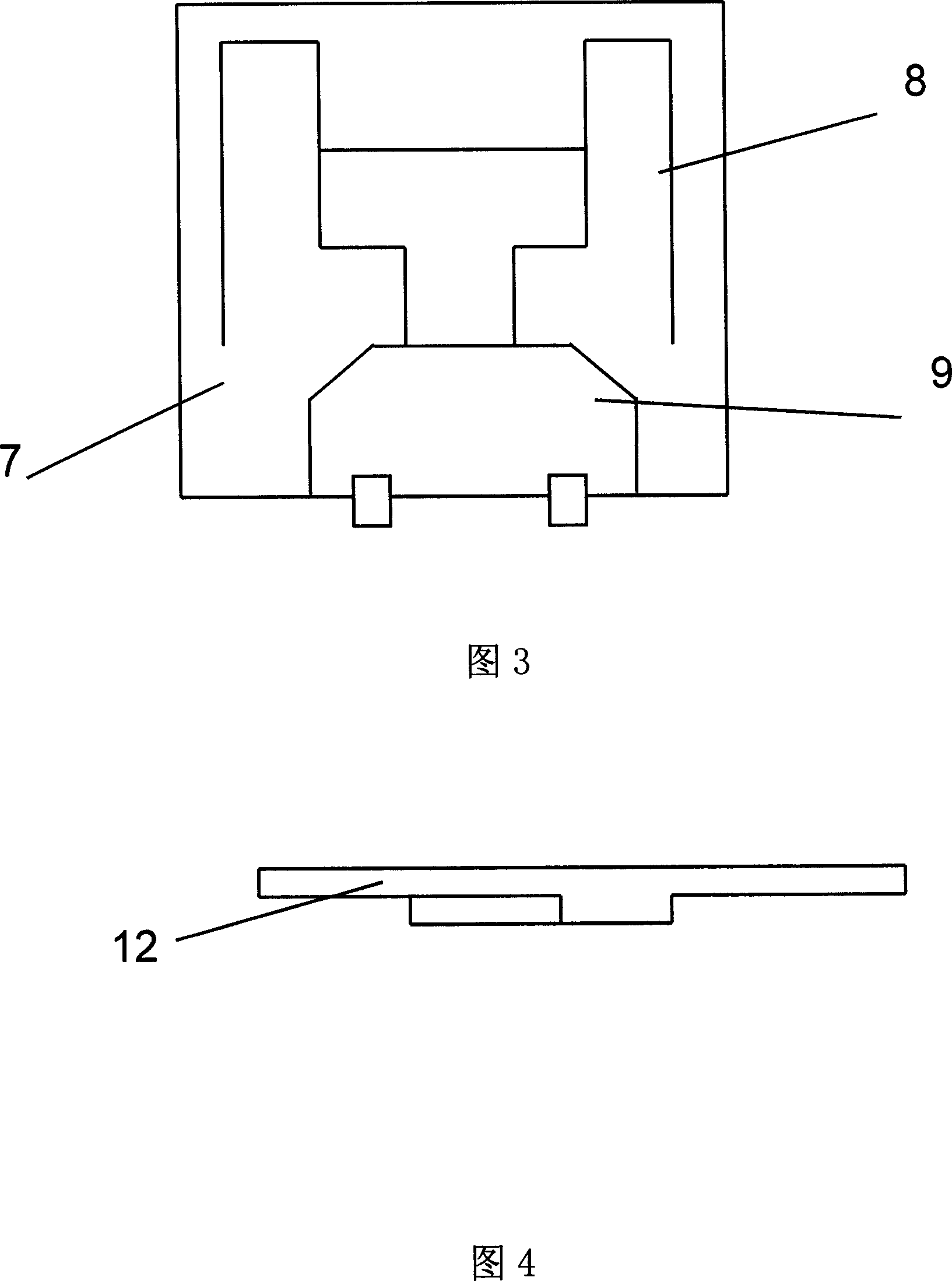
[0029] The technical solutions of the present invention will be further described below in conjunction with the accompanying drawings and through specific implementation methods.

[0030] FIG. 4 is a schematic diagram of the cross-sectional structure of the antenna in this specific embodiment. As shown in Figure 4, a radiation patch 10, a ground patch 11, and a first radio frequency signal transmission line 14 are attached to the upper surface of the dielectric substrate 12, and a second radio frequency signal transmission line 15, a ground signal transmission line 14, and a second radio frequency signal transmission line 15 are attached to the back of the dielectric substrate 12. One end of the radio frequency connector 13 is connected to the second radio frequency signal transmission line 15 , and the other end is connected to the ground signal transmission microstrip line 18 of the microstrip line 18 .

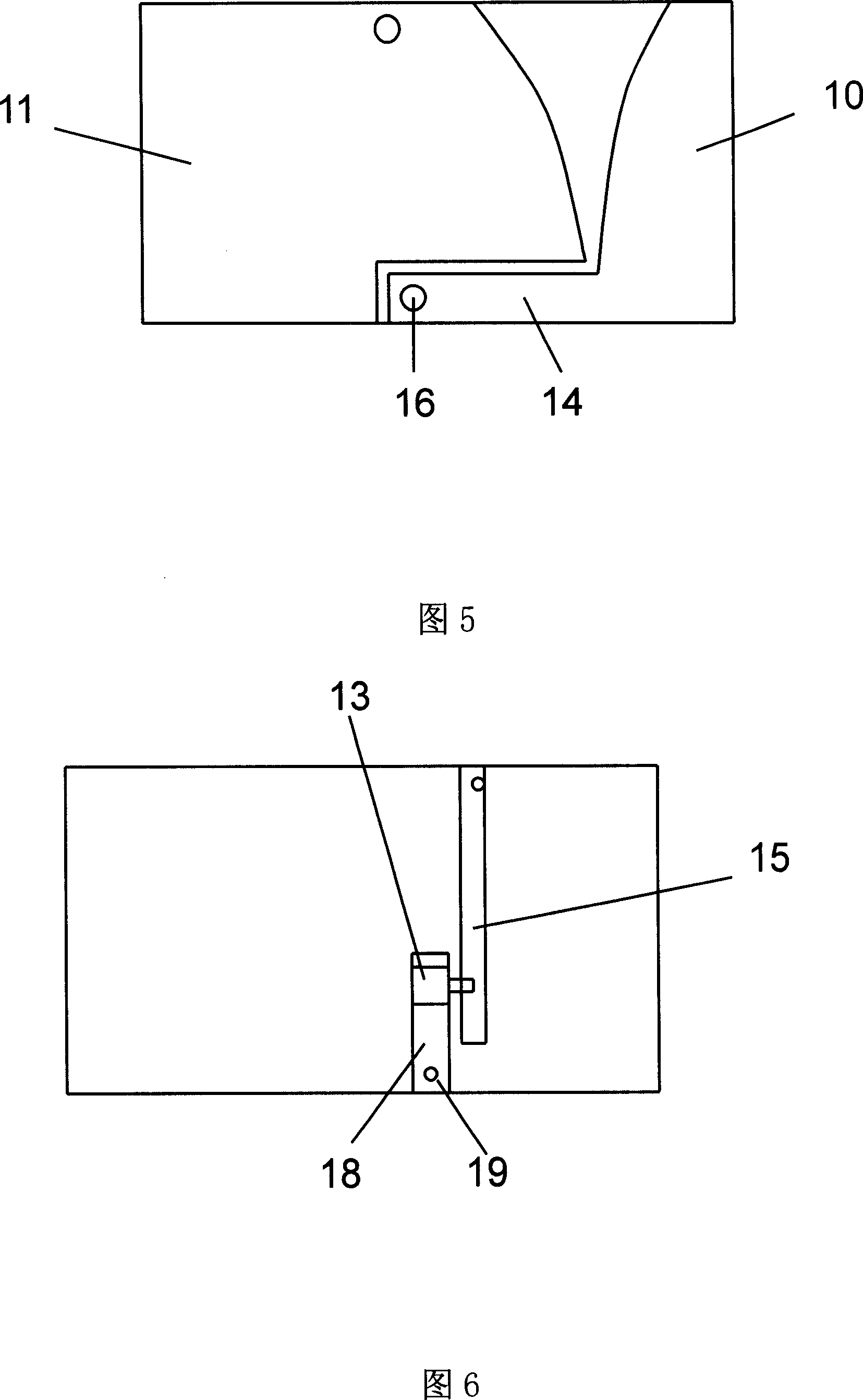
[0031] FIG. 5 is a schematic diagram of the structure of the upper sur...


PUM


Abstract

This invention discloses a kind of antennas including a radiation patch, an earth patch and a medium base plate, said radiation patch and the earth patch are adhered to the top surface of the base plate and a notch port is set between the radiation patch and the earth patch, which can increase gain of antennas.

Description

technical field [0001] The present invention relates to the field of radio frequency technology, in particular to the field of antenna technology. Background technique [0002] With the rapid development of wireless communication technology, more and more information interaction forms of wireless links are used in people's daily production and life. As the terminal of the radio frequency system, the antenna realizes the transmission and reception of signals, and plays a decisive role in the safe and reliable information exchange of the whole system. In the rapidly developing information age, the requirements for antennas are getting higher and higher. It is required to be applied to various forms of radio frequency terminals. The antennas in the traditional sense can no longer meet the needs of the ever-improving integrated circuit technology. Broadband, high gain , simple structure, small and exquisite, and multi-band work have become the focus of modern antenna research. ...

Claims


Application Information

Patent Timeline
Patent Type & Authority Applications(China)
IPC IPC(8): H01Q1/38H01Q13/10H01Q13/08
Inventor 张革军
Owner 张革军
Why Eureka
Try Eureka